Wet-process flue gas desulfurization tower

A wet flue gas desulfurization and tower technology, which is applied in separation methods, chemical instruments and methods, and dispersed particle separation, etc., can solve the problems of poor atomization effect of washing liquid, unsatisfactory dehydration effect, and low probability of nozzle blockage. , to increase the tower section coverage, avoid flue gas channeling, and improve work reliability.

Inactive Publication Date: 2013-10-23
NANNING COLLEGE FOR VOCATIONAL TECH
View PDF4 Cites 12 Cited by
  • Summary
  • Abstract
  • Description
  • Claims
  • Application Information

AI Technical Summary

Problems solved by technology

[0005] The purpose of the present invention is to solve the existing industrial kiln and boiler flue gas spray scrubbing desulfurization tower due to poor cleaning liquid atomization effect, resulting in poor desulfurization effect, easy blockage of nozzles, unsatisfactory dehydration effect after flue gas washing and desulfurization, etc. The problem is to provide

Method used


Image

  • Wet-process flue gas desulfurization tower
  • Wet-process flue gas desulfurization tower
  • Wet-process flue gas desulfurization tower

Examples


Embodiment 1

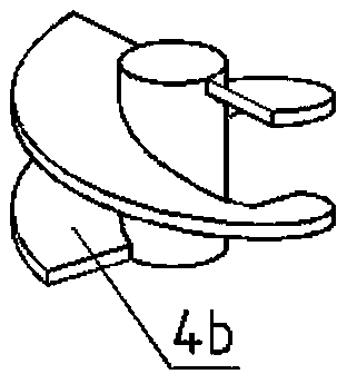
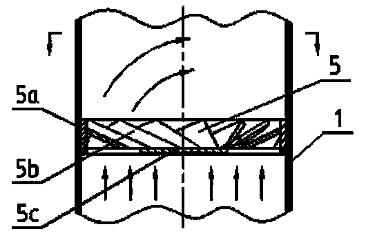
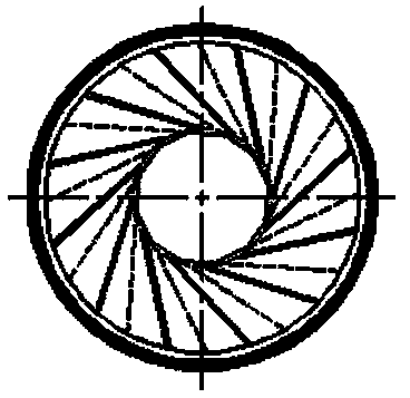
[0033] The sulfur-containing flue gas enters from the flue gas inlet 2 at the lower part of the tower body 1, and rises through a bubble desulfurization zone composed of a sieve plate 3 with a plurality of micropores. When the liquid film of the desulfurization slurry meets, a large number of bubbles are formed, and the bubbles burst to arouse water droplets, water spray, water mist, etc., so that the flue gas can fully contact the slurry, and a part of the sulfur dioxide in the flue gas is absorbed by the desulfurization slurry. The flue gas continues to rise through the liquid mist desulfurization area, and the slurry supply pipe 7 transports the desulfurization slurry to a plurality of low-pressure atomizing nozzles 4 with a short double-helix large flow channel structure, and sprays the desulfurization slurry downward. The short double-helix large flow channel structure The low-pressure atomizing nozzle 4 is composed of a nozzle sleeve 4a and a nozzle core 4b. The bottom of...

Embodiment 2

[0036] The sulfur-containing flue gas enters from the flue gas inlet 2 at the lower part of the tower body 1, and rises through the bubble desulfurization zone composed of two layers of sieve plates 3 with multiple micropores. When the liquid film of the desulfurization slurry meets, a large number of bubbles are formed, and the bubbles burst to arouse water droplets, water spray, water mist, etc., so that the flue gas can fully contact the slurry, and a part of the sulfur dioxide in the flue gas is absorbed by the desulfurization slurry. The flue gas continues to rise through the liquid mist desulfurization area, and the slurry supply pipe 7 transports the desulfurization slurry to a plurality of low-pressure atomizing nozzles 4 with a short double-helix large flow channel structure, and sprays the desulfurization slurry downward. The short double-helix large flow channel structure The low-pressure atomizing nozzle 4 is composed of a nozzle sleeve 4a and a nozzle core 4b. The ...

Embodiment 3

[0040] The sulfur-containing flue gas enters from the flue gas inlet 2 at the lower part of the tower body 1, and rises through a bubble desulfurization zone composed of a sieve plate 3 with a plurality of micropores. The liquid films of the prepared desulfurization slurry meet to form a large number of bubbles, and the bubbles burst to arouse water droplets, water spray, water mist, etc., so that the flue gas can fully contact the slurry, and a part of the sulfur dioxide in the flue gas is absorbed by the desulfurization slurry. The flue gas continues to rise through the liquid mist desulfurization area, and the slurry supply pipe 7 transports the desulfurization slurry to a plurality of low-pressure atomizing nozzles 4 with a short double-helix large flow channel structure, and sprays the desulfurization slurry downward. The short double-helix large flow channel structure The low-pressure atomizing nozzle 4 is composed of a nozzle sleeve 4a and a nozzle core 4b. The bottom of...


PUM


Abstract

The invention provides a wet-process flue gas desulfurization tower to well solve the technical problems of poor desulphurization effect, unreliable equipment operation caused by nozzles obstructed by foreign materials such as fouling fragments and the like, poor spray removal effect after flue gas washing and desulphurization which are all caused by poor slurry atomization effect of a present industrial kiln and boiler flue gas spraying washing type desulfurization tower. According to the invention, desulphurization efficiency and operational reliability are raised by improving the desulphurized slurry atomization effect and nozzle passageways; due to improvement of the nozzles, pressure requirements on desulphurized slurries are low, nozzle blocking probability is reduced, and removal rate of sulfur dioxide is raised; and a routine cyclone dehydrator structure is improved, rising cyclone diameter of flue gas is increased, the flue gas dehydration and demisting effect after washing is raised, and corrosion and dirt deposition of downstream flues and equipment are decreased. The wet-process flue gas desulfurization tower provided by the invention has characteristics of high desulphurization efficiency, good spray removal effect, simple structure, high operation reliability and the like, can be adopted to effectively reduce investment and operation costs, and is suitable for a wet flue gas desulphurization technology.

Description

technical field [0001] The invention relates to an intermediate device of desulfurization equipment, in particular to a wet flue gas desulfurization tower. Background technique [0002] At present, the flue gas desulfurization methods include dry flue gas desulfurization technology, spray dry flue gas desulfurization technology, fly ash dry flue gas desulfurization technology, wet flue gas desulfurization technology, etc. The process, form and mechanism are similar, mainly using limestone (CaCO 3 ), quicklime (CaO) or sodium carbonate (Na 2 CO 3 ) and other slurries are used as detergents, and the flue gas is washed in the reaction tower to remove SO in the flue gas 2 . This process has a history of 50 years. After continuous improvement and perfection, the technology is relatively mature, with high desulfurization efficiency (90%-98%), large unit capacity, strong adaptability to coal types, low operating costs and by-products Easy recycling and other advantages. Howev...

Claims


Application Information

Patent Timeline
IPC IPC(8): B01D53/80B01D53/50
Inventor 徐海枝麦艳红农德宣何工上韦联琦甘善泽韦瑞录
Owner NANNING COLLEGE FOR VOCATIONAL TECH
Why Eureka
Try Eureka