
Dual metal joint interface metallographic etching agent and display method

A bimetallic joint and metallographic structure technology, applied in the field of chemical analysis, can solve the problems of not being able to meet the needs of production and analysis, the severe reaction process of strong oxidants, the influence of steel-based metal structure corrosion, etc., to improve performance improvement and failure analysis The effect of inspection ability, stable and easy control of the reaction process, and simple corrosion method

Active Publication Date: 2013-10-23
ANGANG STEEL CO LTD
View PDF3 Cites 14 Cited by
  • Summary
  • Abstract
  • Description
  • Claims
  • Application Information

AI Technical Summary

Problems solved by technology

In particular, the corrosion resistance of copper alloy / steel is quite different. Currently, the corrosive agents for single copper metal or acid solutions containing high-concentration nitric acid solution, ferric chloride hydrochloric acid solution, etc., are not effective for copper-based metal corrosion. At the same time, it will have different degrees of corrosion effects on the steel-based metal structure, or the strong oxidant reaction process is severe. When it is applied to the corrosion of bimetallic joints, it is difficult to control the corrosion process and effect, the success rate is low, and it is impossible to obtain clear boundaries. Joint metallographic structure
In addition, methods such as adding a syringe and controlling the flow direction of the reagent during corrosion also make the process complicated and difficult to operate, and it is impossible to guarantee a clear boundary structure. Therefore, the existing methods can no longer meet the needs of production and analysis.

Method used


Image

  • Dual metal joint interface metallographic etching agent and display method
  • Dual metal joint interface metallographic etching agent and display method
  • Dual metal joint interface metallographic etching agent and display method

Examples


Embodiment Construction

[0020] The method of the present invention will be described in detail below in conjunction with specific embodiments of the present invention.

[0021] to 20 # The structure of a steel-clad brass alloy (containing about 62% copper by mass percentage) layered metal composite member is taken as an example.

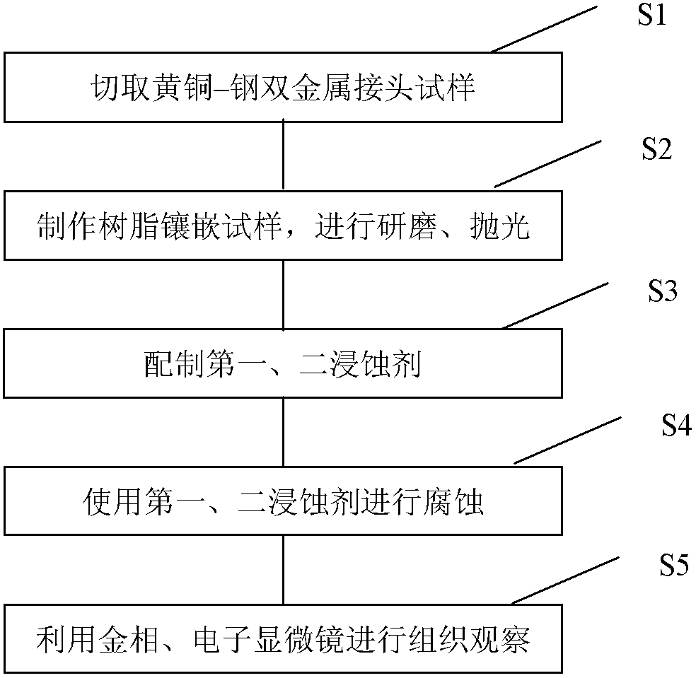
[0022] Such as figure 1 as shown,

[0023] 1 Execute step S1 to sample

[0024] First, at the joints of the components to be analyzed, use the wire cutting method that has the least impact on the interface to intercept the analysis sample with metal on both sides. The length of the sample is 10*15mm.

[0025] 2 Execute step S2 to make a metallographic sample

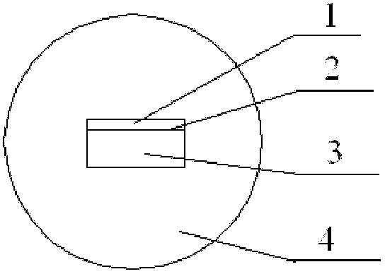
[0026] (1) Put the sample cut in step S1 into the sample mounting machine for resin mounting, and make a metallographic mounting sample with the interface transverse section as the analysis surface, and its structure is as follows figure 2 shown in .

[0027] (2) Use 500 # , 800 # 、1000 # , 1200 # Fine-grit...


PUM


Abstract

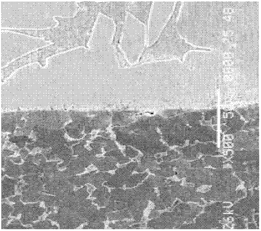
The invention discloses a dual metal joint interface metallographic etching agent and a display method. The dual metal joint interface metallographic etching agent comprises the following components: a first etchant which is a mixed solution prepared from 6-10% of H2O2 water solution and 27% of ammonia water according to the volume ratio of 1 to 1, a saturated aqueous solution with 0.5-1 ml of potassium dichromate, and a second etchant which is 4-6% of HNO3 anhydrous ethanol solution by volume. The method comprises the steps of: sampling, preparing a sample, preparing an etching reagent, and displaying and obtaining a metallographic structure map of the sample. The agent disclosed by the invention is easily prepared; a copper and copper alloy / steel dual metal composite material joint interface structure can be rapidly and clearly displayed; and test and analysis of related performances of the novel composite material can be accurately carried out. By adopting the dual metal joint interface metallographic etching agent, performance improvement and failure analysis inspection abilities of a dual metal composite material member can be improved; and the etching agent has important directive significance on production and use.

Description

technical field [0001] The invention belongs to the field of chemical analysis, and relates to a bimetallic joint interface metallographic structure corrosion reagent and a display method, in particular to a copper alloy / steel bimetallic joint interface metallographic structure corrosion reagent and a display method. technical background [0002] Bimetallic composite material is a new type of material that combines the advantages of physical, chemical, mechanical properties and price differences of two materials. In recent years, bimetallic composite materials have been rapidly developed and widely used in manufacturing and production. Metal composite materials such as copper-clad aluminum, copper-clad steel, and copper-plated steel have begun to be widely used. Some equipment manufacturers use bimetallic materials to replace the original single precious metal parts and components in order to reduce costs. The composite material parts of the equipment will have failure def...

Claims


Application Information

Patent Timeline
IPC IPC(8): G01N1/32C23F1/18C23F1/28C23F1/34C23F1/40
Inventor 王晓峰李文竹隋晓红张鹏远黄磊马惠霞高玉明
Owner ANGANG STEEL CO LTD
Learn More