Deep ultraviolet laser Raman spectrometer

A technology of Raman spectrometer and deep ultraviolet, which is applied in the field of Lapp spectrometer, can solve the problems of easy damage to eyes and vision

Inactive Publication Date: 2013-10-23
湖北省天门市鹰飞拓检测仪器股份有限公司
View PDF9 Cites 25 Cited by
  • Summary
  • Abstract
  • Description
  • Claims
  • Application Information

AI Technical Summary

Problems solved by technology

[0007] (5) Easy to damage eyesight

Method used


Image

  • Deep ultraviolet laser Raman spectrometer
  • Deep ultraviolet laser Raman spectrometer
  • Deep ultraviolet laser Raman spectrometer

Examples


Embodiment 1

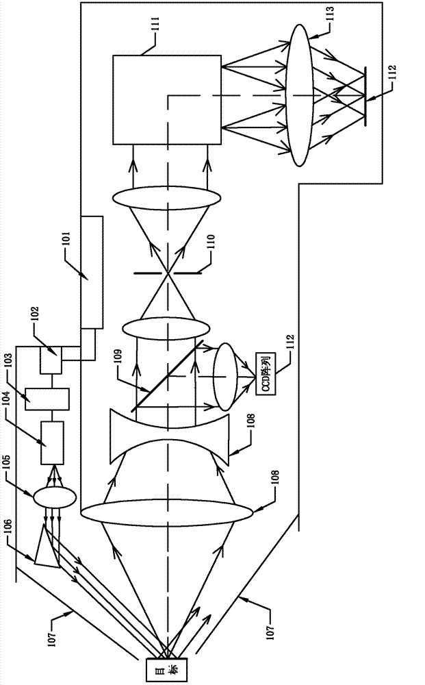
[0026] Such as figure 1 Shown is the optical path diagram of the Raman-Lapp instrument with off-axis illumination, including the light source generating device, external optical path, dispersion system, and receiving system. The light source generating device is composed of a signal printed circuit board 101, a battery 102, a modulator 103 and a luminous tube 104; the external optical path includes a beam expander 105, a mirror 106, a mirror emitting laser slot 107 and a lens 108; the dispersion system Including a beam splitter 109 , a slit 110 and a grating 111 , the receiving system includes a CCD imaging system 112 and a spectrum mirror 113 . Firstly, the light source generating device is turned on, then the luminous tube 104 emits a laser with a wavelength of 785 nanometers, the laser passes through the beam expander 105 to change the diameter of the laser, and then the mirror 106 emits the laser with the changed diameter to the detector. On the target, the detection targ...

Embodiment 2

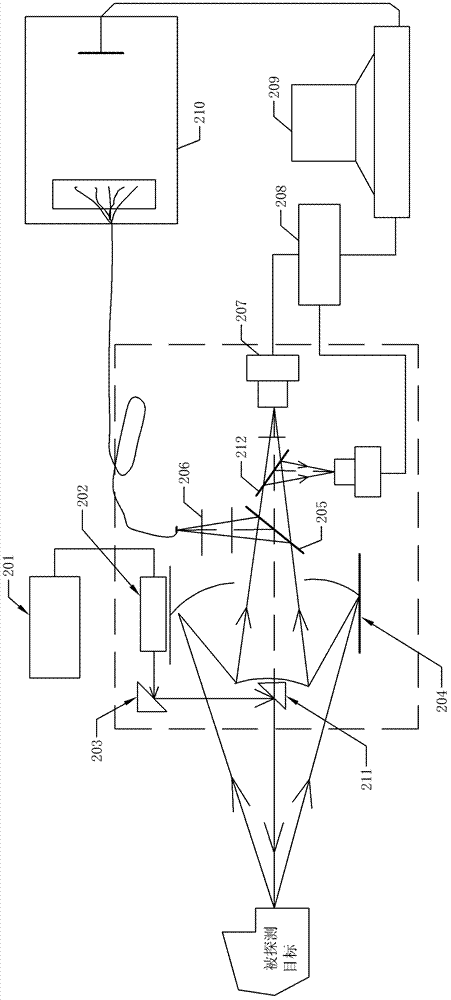
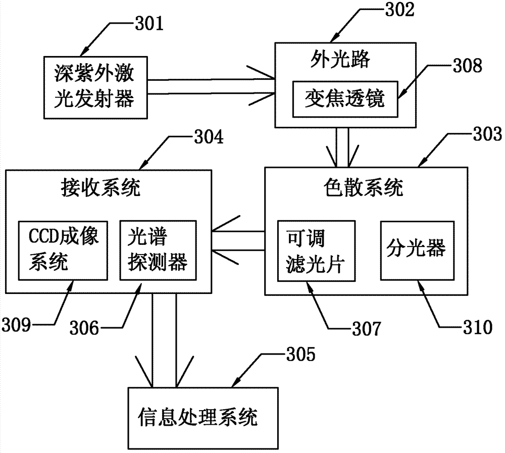
[0033] Such as Figure 5 Shown is the long-distance optical path diagram of the deep ultraviolet laser Raman Lap instrument of the present invention, combined with image 3 , wherein the laser emitted by the deep ultraviolet laser transmitter 301 is a deep ultraviolet laser with a wavelength of 213 nanometers; the external optical path 302 is composed of a beam expander 501, mirrors 502, 503, Cassegrain telescope 504, and a lens 505; Described dispersion system 303 is made up of beam splitter 506,508, notch filter 507, adjustable filter 307, lens 509,511,515, band-pass filter 510, and described beam splitter 506 is a short-pass filter , the beam splitter 503 is a long-pass filter, and a pinhole 512 is provided between the mirror 502 and the mirror 503, and a grating 513 is provided between the Cassegrain telescope 504 and the beam splitter 506; The receiving system 304 is composed of a CCD array in the CCD imaging system 309, a photomultiplier tube 514, and an avalanche tube ...


PUM

PropertyMeasurementUnit
wavelengthaaaaaaaaaa

Abstract

The invention relates to the field of Raman spectrometers, and discloses a deep ultraviolet laser Raman spectrometer which comprises a deep ultraviolet laser emitter, a reflector path, a chromatic dispersion system, a receiving system and an information processing system, wherein the deep ultraviolet laser emitter, the reflector path, the chromatic dispersion system, the receiving system and the information processing system are sequentially connected; the wavelength of a laser emitted by the deep ultraviolet laser emitter is within a range of 210-230 nanometers; an optical splitter adopted at the front end of the reflector path is a short-pass optical filter; the chromatic dispersion system is an adjustable optical filter. The deep ultraviolet laser Raman spectrometer disclosed by the invention has the characteristics of high sensitivity, large illumination point and high resolution and avoids the eyesight impairment.

Description

technical field [0001] The invention relates to the field of Lapp spectrometers, in particular to a deep ultraviolet laser Lapp spectrometer. Background technique [0002] Raman spectrum is a kind of scattering spectrum. In 1928, C.V. Raman discovered that the frequency of light scattered by molecules changes when light passes through a transparent medium. This phenomenon is called Raman scattering. It was also observed in the Soviet Union and France later that same year. In the scattering spectrum of a transparent medium, the component with the same frequency as the incident light frequency υ0 is called Rayleigh scattering; the spectral line or band υ0±υ1 that is symmetrically distributed on both sides of υ0 is the Raman spectrum. Raman spectroscopy is an analysis method based on the unique effect of Raman scattering, which analyzes the scattering spectrum with a frequency different from that of the incident light to obtain molecular vibration and rotation information, a...

Claims


Application Information

Patent Timeline
Patent Type & Authority Applications(China)
IPC IPC(8): G01N21/65
Inventor 白燕张幼文
Owner 湖北省天门市鹰飞拓检测仪器股份有限公司
Why Eureka
Try Eureka