Bypass purification system for treating slightly polluted river water

A purification treatment, cement technology, applied in the direction of water/sewage multi-stage treatment, water/sludge/sewage treatment, chemical instruments and methods, etc., can solve the problems of lax management of sewage discharge and sudden drop in the sewage capacity of rivers, etc. Achieve the effects of preventing short water areas and dead water areas, cheap performance, and saving operating costs

Inactive Publication Date: 2013-11-06
INST OF URBAN ENVIRONMENT CHINESE ACAD OF SCI
View PDF3 Cites 11 Cited by
  • Summary
  • Abstract
  • Description
  • Claims
  • Application Information

AI Technical Summary

Problems solved by technology

Sewage discharge management in some areas is not strict, so that industrial wastewater and domestic sewage are directly dischar

Method used


Image

  • Bypass purification system for treating slightly polluted river water
  • Bypass purification system for treating slightly polluted river water

Examples


specific Embodiment approach 1

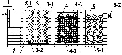
[0030] Embodiment 1: The outlet water of the sedimentation tank 1 enters the nitrification section 3 through the inlet pipe 2-1 through the corridor 2 and the bottom inlet pipe 2-2; the water flows through the filler 3-1, passes through the top of the nitrification section 3, and enters the denitrification through the corridor The bottom of the denitrification section enters the denitrification section 4; the water is discharged from the top of the denitrification section 4 through the packing 4-2 and 4-1, and enters the bottom of the adsorption phosphorus removal section through the corridor, and then enters the adsorption phosphorus removal section 5; the phosphorus removal is carried out through the packing 5-1 Finally, it is discharged through the outlet pipe 5-2.

specific Embodiment approach 2

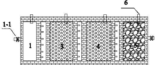
[0031] Specific implementation mode two: combination figure 1 and figure 2To illustrate this embodiment, the patent of the invention includes nitrification section, denitrification section and adsorption dephosphorization section, and the fillers in the nitrification section are all filled with zeolite; the denitrification filler layer includes an upper layer and a lower layer, that is, a zeolite layer and a slow-release carbon source (rotting wood) layer , the upper layer is a zeolite layer, the particle size range is 5-10mm, and the lower layer is rotten wood chips cut from rotten wood; the adsorption and phosphorus removal section is all filled with cement bricks, and the particle size range is 5cm.

specific Embodiment approach 3

[0032] Specific implementation mode three: combination figure 1 and figure 2 This embodiment is described. In this embodiment, deflectors are arranged between each section to form a water inlet corridor, thereby realizing an upward water inlet mode. The water entering the sedimentation tank 1 enters the nitrification section 3 through the corridor 2, and each section enters and exits the water through a similar cycle, which effectively reduces the hydraulic dead zone of each section and ensures a good hydraulic flow state inside the system. Other components and connections are the same as those in the first embodiment.

[0033] Specific implementation mode four: combination figure 1 and figure 2 Describe this embodiment, this embodiment fills packing in nitrification section 3, denitrification section 4 and adsorption dephosphorization section 5, and the filler of nitrification section 3 is the zeolite with good ammonia nitrogen adsorption capacity, and the filler of adso...


PUM

PropertyMeasurementUnit
Particle sizeaaaaaaaaaa

Abstract

The invention relates to a waste water treatment device which is a land treatment device applicable to slightly polluted river water treatment and treated water recycling, particularly to a bypass purification system for intensively treating slightly polluted river water. According to the bypass purification system, waste water sequentially flows through a nitrification section, a denitrification section and an adsorption dephosphorization section. The bottom of the denitrification section is filled with rotten wood as a controlled-release carbon source to solve the problem of insufficient denitrification carbon sources for the river water, so that the denitrification efficiency of the system to the slightly polluted river water is improved. The system is filled with packing with large specific surface areas, developed pores and good adsorption capacities, such as zeolite and cement bricks, so that the biological holding volume of the system is improved greatly, and high phosphate and nitrogen removing efficiencies are guaranteed. The bypass purification system has the advantages of being simple in structure, multiple in function, efficient, low in cost, easy to operate and manage, stable in operate, capable of achieving synchronous decarburization and dephosphorization and the like, treated water can be recycled directly, and the system can be combined with ecological construction and town afforestation functions.

Description

technical field [0001] The patent of the present invention relates to a bypass purification system for treating slightly polluted river water. It belongs to the field of water pollution control. Background technique [0002] River pollution has become a global problem, and river and wetland ecosystems have become the most threatened ecosystems. Relatively speaking, European and American countries realized this serious problem earlier than my country, and began to restore rivers in the 1940s, and began large-scale deployment in the 1990s. Since the 1980s, with the increasing intensity of reform and opening up in my country, the urbanization process has also entered a stage of rapid development, causing many rivers to repeat the mistakes of Western countries. After the mid-1990s, the increasingly serious problem of river pollution has aroused strong public concern, and our country has also launched river pollution control projects one after another. With the rapid developme...

Claims


Application Information

Patent Timeline
IPC IPC(8): C02F9/14
Inventor 刘超翔向衡刘琳
Owner INST OF URBAN ENVIRONMENT CHINESE ACAD OF SCI
Why Eureka
Try Eureka