Automatic cell welding machine for small solar component

A technology for solar battery packs and solar cells, applied in welding equipment, welding equipment, laser welding equipment, etc., can solve the problems of high labor intensity, high defect rate, low welding efficiency, etc., so as to reduce labor intensity and improve production efficiency. and welding yield, easy operation effect

Active Publication Date: 2013-11-13
WINCHANCE TECH
View PDF7 Cites 14 Cited by
  • Summary
  • Abstract
  • Description
  • Claims
  • Application Information

AI Technical Summary

Problems solved by technology

Manual soldering is not only labor-intensive and low in welding efficiency, but also due to the relatively small material area of ​​the small component itself, manual operation needs to be relatively skilled. When operating with a hand-held electric soldering iron, there will be burns in case of misoperation, and due to manual operation methods and Depending on the force and contact time, it is easy to cause false welding or overweight welding to damage the battery, resulting in a high defect rate

Method used


Image

  • Automatic cell welding machine for small solar component
  • Automatic cell welding machine for small solar component
  • Automatic cell welding machine for small solar component

Examples


Embodiment 1

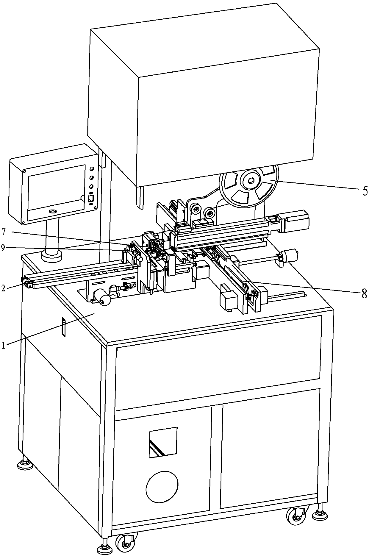
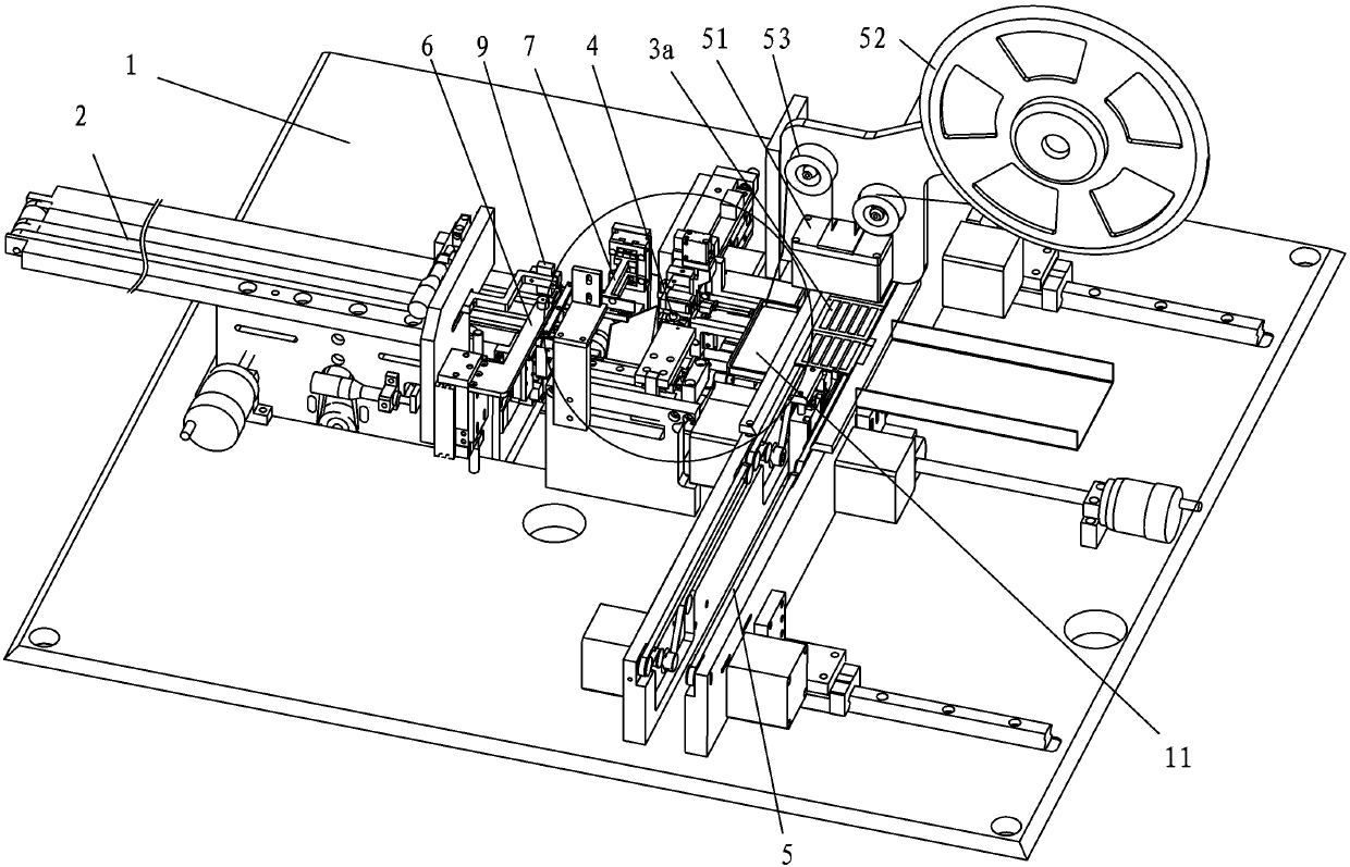
[0049] In this embodiment, the slicing mechanism 3 includes a pair of first presser feet 31, a top plate 32, a presser foot cylinder and a top plate cylinder. A pair of first pressing feet 31 are arranged opposite to each other up and down, and a pair of first pressing feet 31 and a top plate 32 are sequentially arranged at the discharge end of the conveyor belt 2 along the feeding direction. The upper first presser foot 31 is connected to the piston rod of the presser foot cylinder, and the action of clamping and unclamping the solar cell stack sheet 1a is realized through the telescopic action of the piston rod of the presser foot cylinder. The top plate 32 is connected to the piston rod of the top plate cylinder. When the piston rod of the top plate cylinder is extended, the top plate 32 is driven to move upward, and the top plate 32 is pressed against the exposed part of the solar cell panel 1a sandwiched between the pair of first pressers 31 And separate one solar cell she...

Embodiment 2

[0052] In this embodiment, the splitting mechanism 3 includes two pairs of first presser feet and two presser foot cylinders. Each pair of first presser feet is set up and down correspondingly, two pairs of first presser feet are arranged side by side on the discharge end of the conveyor belt 2, two pairs of first presser feet are respectively connected to the piston rod of a presser foot cylinder, two pairs of first presser feet respectively The staggered lifting is realized by the respective presser foot cylinders, as described below.

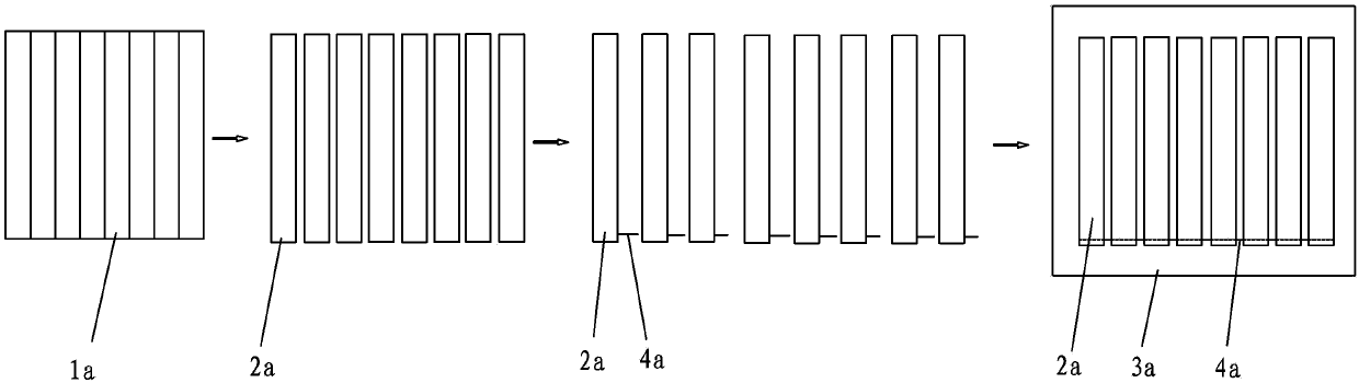
[0053] Firstly, a cut is cut on the front or back of the solar cell assembly sheet 1a, and the solar cell assembly sheet 1a is divided into a plurality of solar cell sheets 2a with a predetermined width. When the solar cell stack sheet 1a enters the two pairs of first presser feet, the two pairs of first presser feet clamp the solar cell sheet 2a by their respective cylinders. One pair of the first presser foot is slightly shifted relative to t...

Embodiment 3

[0055] Compared with the first embodiment, this embodiment also includes an infrared cutting mechanism, which can generate a laser beam. The laser beam emitting end of the infrared cutting mechanism corresponds to the feeding end of a pair of first presser feet 31. The front or back of the battery sheet 1a is cut with a number of cut marks, thereby dividing the solar battery sheet 1a into a plurality of solar battery sheets 2a with a predetermined width. Then, the solar cell assembly sheet 1a is divided into the solar cell sheets 2a along the cut by the dislocation and slicing method in the foregoing embodiments.

[0056] The welding mechanism 4 includes a soldering station 41, a soldering iron 42, a second presser foot, a soldering iron cylinder, and a second presser foot cylinder. The soldering station 41 is fixed on the worktable 1 and is arranged between the output end of the slicing mechanism 3 and the placement output mechanism 8. The second presser foot and the soldering i...


PUM


Abstract

The invention discloses an automatic cell welding machine for a small solar component. The automatic cell welding machine comprises a conveyor belt and a cell separation mechanism, which are sequentially connected along the feeding direction of a solar cell component. The automatic cell welding machine also comprises a welding strip conveying mechanism, a first suction mechanical hand, a welding mechanism, a second suction mechanical hand and a placement output mechanism. According to the automatic cell welding machine for the small solar component, the solar cell component is separated into independent solar cells through the cell separation mechanism, and a welding strip is welded on the back surfaces of the solar cells through the welding mechanism to connect electrodes of circuits in the solar cells. A staggered cell separation mode is adopted, so that the automatic cell welding machine is easy to operate, the production efficiency and the welding yield can also be improved, the labor intensity can be reduced, and the problems of high breaking rate of manual cell separation of the conventional small cell component, high pseudo welding rate and high component damage rate of the small component and high industrial accident rate are solved.

Description

Technical field [0001] The invention relates to a packaging device for solar small components, in particular to a device for slicing and soldering solar cells. Background technique [0002] In the packaging process of solar modules, especially small solar cell modules, the slicing and welding of solar cells is a very important process, and the quality of the welding directly affects the reliability of solar cell modules. [0003] At present, the slicing of battery slices is mainly carried out manually, such as figure 1 As shown, firstly, a cutting mark is made on the front of a large solar cell sheet according to a set prescribed size to form a solar cell assembly sheet 1a. Then manually break the solar cell stack sheet 1a into a small piece of solar cell sheet 2a, solder a soldering tape 4a on the back of each solar cell sheet 2a, and connect the soldering tape 4a to the electrode of the circuit in the solar cell sheet 2a, and then Then stick multiple solar cells 2a on the substr...

Claims


Application Information

Patent Timeline
Patent Type & Authority Applications(China)
IPC IPC(8): B23K28/02B23K37/00
CPCB23K3/00B23K3/08B23K26/38B23K28/02B23K31/125B23K37/00
Inventor 陈文良陈沧国张国营陈志刚
Owner WINCHANCE TECH
Why Eureka
Try Eureka