Technique for fast filling constructed wetland in shore area

A technology of artificial wetland and process method, applied in civil engineering, rapid filling of artificial wetland in the lakeside area, can solve the problems of high cost, low construction efficiency, difficult consolidation and rapid formation, etc., to improve productivity and reduce engineering. Cost, reduce the effect of rework

Active Publication Date: 2015-01-21
ANHUI SURVEY & DESIGN INST OF WATER CONSERVANCY & HYDROPOWER
View PDF4 Cites 0 Cited by
  • Summary
  • Abstract
  • Description
  • Claims
  • Application Information

AI Technical Summary

Problems solved by technology

This method can complete the dredging, transporting and unloading of mud at one time, with high efficiency and low cost, but the particles after dredging and filling are very fine, and it is difficult to consolidate and quickly form landscape water bodies such as sub-lakes and waterways; the other It is a barge transportation method. In this method, the soil material at the bottom of the lake is excavated by the hydraulic grab installed on the ship and directly unloaded onto the adjacent mud barge, and the soil material is transported by the mud barge to the wetland filling area. The hydraulic backhoe unloads the soil from the soil transport and mud barge, and finally it is leveled by the wetland excavator. After excavation by this method, the soil becomes lumpy, and the soil consolidates quickly after filling. After the construction is completed, the beach surface can be directly used. Easy to form, but low construction efficiency and high cost

Method used


Image

  • Technique for fast filling constructed wetland in shore area
  • Technique for fast filling constructed wetland in shore area
  • Technique for fast filling constructed wetland in shore area

Examples


Embodiment 1

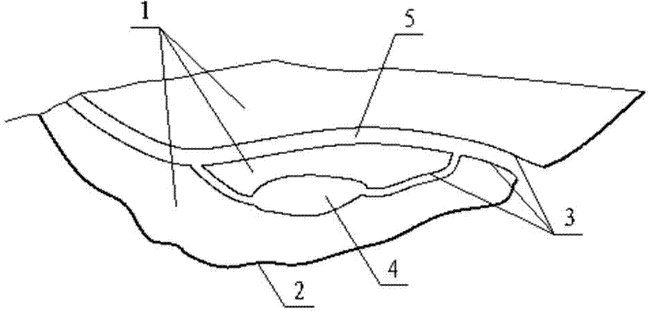
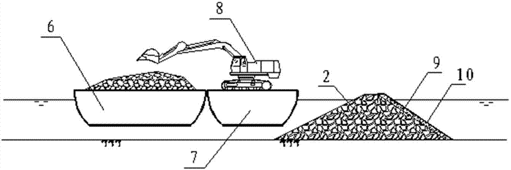
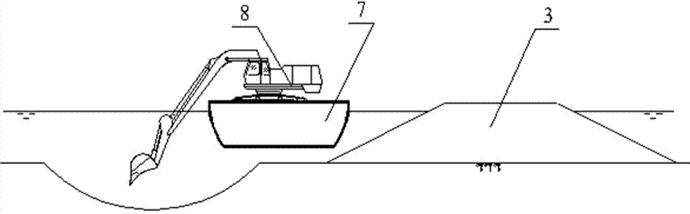
[0036] Such as figure 1 As shown, the shoreline of a city’s lakeside artificial wetland test section project is about 1800m long, with an average width of about 500m, the front and periphery of the wetland in the lake area are about 2450m long, and the wetland area is about 802,300m 2 , 941,000 m of filled earthwork 3 , there are sub-lakes 4, waterways 5 and other landscape water bodies. The wetland filling period is required to be 4 months, and plant measures can be carried out on it immediately after the filling is completed. Although conventional cutter suction dredger dredging construction can meet the construction period requirements, the wetland bearing capacity after filling cannot meet the requirements, and water body landscapes such as sub-lakes and waterways are difficult to organize and form. The construction scheme of grab dredger with mud barge has low construction efficiency, it is difficult to meet the construction period requirements, and the construction cos...


PUM


Abstract

The invention discloses a technique for fast filling a constructed wetland in a shore area. A jetty and a separation cofferdam are adopted to divide the wetland into a plurality of hydraulic reclamation areas as required; each hydraulic reclamation area is constructed independently, so that the construction production efficiency is improved and the construction period is shortened. A bucket-wheel type dredger instead of a common cutter suction dredger is adopted to perform hydraulic reclamation construction, the discharged soil is small blocks, has the characteristic of partial saturation, is relatively shorter in solidification time, and can meet the requirement of planting plants in the wetland in short time. The bucket-wheel type dredger is utilized to borrow earth from a lake region, and the borrow pit of the separation cofferdam is filled and leveled up in an equal quantity replacement manner by adopting the hydraulic reclamation manner, so that the production efficiency is effectively improved, the project cost is reduced, and the cost is decreased. A high-strength geotechnical cloth is arranged on the inner side of the jetty, so that the hydraulic reclamation earthwork in the wetland is prevented from entering the lake region through the holes of the jetty, and the pollution to the lake water is reduced; the water permeability of the high-strength geotechnical cloth enables the water bodies of the wetland and the lake to communicate, and the influence on the wetland environment is avoided.

Description

technical field [0001] The invention belongs to the technical field of ecological environment construction and environmental protection, and relates to civil engineering, in particular to a process for rapidly filling artificial wetlands in the lakeside area. Background technique [0002] Lakeside wetlands play an important role in restoring the ecological environment of lakes, purifying lake water bodies, and reducing wind and wave erosion. However, with the development of society, the discharge of sewage, dumping of garbage, point source pollution and non-point source pollution in the region have severely damaged the lakeside wetland ecosystem, which has been unable to play the functions of regulating water quality and protecting ecology. Combined with lake sediment dredging, soil borrowing from the lake is used to fill the lakeside artificial wetland and restore aquatic plants and other organisms, which is one of the methods. [0003] At present, there are two main metho...

Claims


Application Information

Patent Timeline
Patent Type & Authority Patents(China)
IPC IPC(8): E02D17/18
Inventor 檀少彬骆克斌徐金朱青黎平平金永强武杰许田地潘正丰董志红余婷
Owner ANHUI SURVEY & DESIGN INST OF WATER CONSERVANCY & HYDROPOWER
Why Eureka
Try Eureka