Device and method for compressing pipeline magnet leakage signal data

A signal data, compression device technology, applied in pipeline systems, material magnetic variables, mechanical equipment, etc., can solve problems such as low compression ratio, limited pipeline space, and small data storage device volume and storage space, to reduce distortion, The effect of reducing memory consumption and easy hardware implementation

Active Publication Date: 2013-11-20
NORTHEASTERN UNIV
View PDF5 Cites 18 Cited by
  • Summary
  • Abstract
  • Description
  • Claims
  • Application Information

AI Technical Summary

Problems solved by technology

However, the space in the pipeline is limited, resulting in a small volume and storage space of the equipment for storing data, so data compression must be performed on the pipeline MFL detection data
Traditional lossless compression methods, such as Huffman coding, arithmetic coding and entropy coding, and lossless predictive coding can realize data lossless compression, but the compression ratio is very low; lossy predictive coding and transform coding have relatively large compression ratios, but in When compressing magnetic flux leakage signal data, the loss of a large amount of important information caused by lossy compression is unacceptable
In the existing pipeline magnetic flux leakage data compression methods, lossless compression is mostly used, and its compression ratio is relatively low, which is not conducive to the improvement of detection accuracy and the extension of the detection pipeline length.

Method used


Image

  • Device and method for compressing pipeline magnet leakage signal data
  • Device and method for compressing pipeline magnet leakage signal data
  • Device and method for compressing pipeline magnet leakage signal data

Examples


Embodiment Construction

[0070] Embodiments of the present invention will be further described in detail below in conjunction with the accompanying drawings.

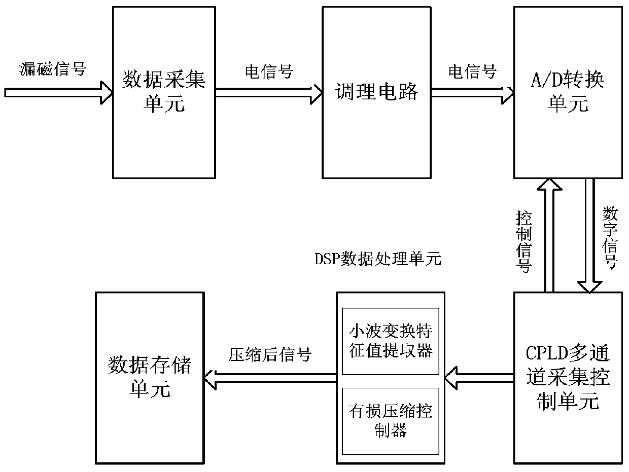
[0071] This embodiment provides a structural block diagram of a pipeline magnetic flux leakage signal data compression device, as figure 1 shown. It is composed of data acquisition unit, conditioning circuit, A / D conversion unit, CPLD multi-channel acquisition control unit, DSP data processing unit and data storage unit.

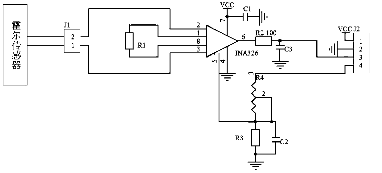
[0072] figure 2 It is the circuit schematic diagram of the conditioning circuit, and the conditioning circuit realizes filtering and amplification of the electrical signal collected by the Hall sensor. In this example, the SS495A Hall sensor is used to detect the magnetic flux leakage signal. The output of the Hall sensor is filtered by the capacitor and resistor, and then the signal is amplified by the operational amplifier INA326, and finally the output signal is sent to the AD conversion unit.

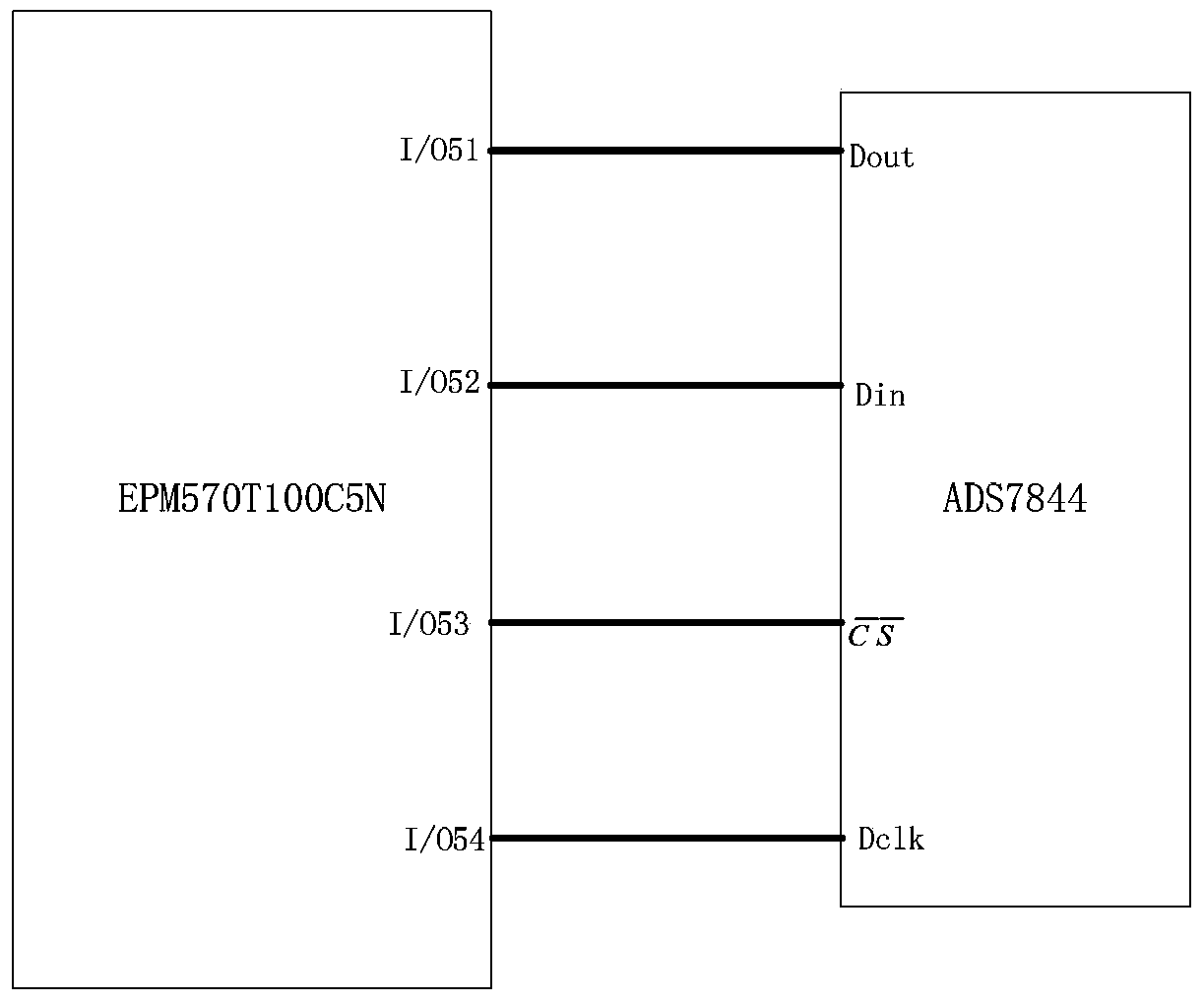
[0073] image 3 It is ...


PUM


Abstract

The invention discloses a device and method for compressing pipeline magnet leakage signal data and belongs to the technical field of non-destructive testing. The method comprises the steps that step 1, a pipeline magnet leakage signal is collected and converted to an electric signal, and after filtering amplification is conducted, the electric signal is further converted to a digital signal; step 2, feature parameter extraction is conducted on the digital signal output from the step 1 through the wavelet transforming arithmetic based on a self-adaptation threshold value, a one-dimensional magnet leakage signal is converted to a two-dimensional magnet leakage signal, integer wavelet transformation is conducted on the two-dimensional magnet leakage signal so that a wavelet coefficient matrix can be obtained, and therefore important information of the magnet leakage signal is concentrated in the low-frequency portion of the wavelet transformation coefficient; step 3, lossy compression is conducted on the wavelet coefficient matrix through the improved SPIHT arithmetic. Compared with the prior art, the device and method for compressing the pipeline magnet leakage signal data overcome the shortages that the compression rate when the non-destructive compression is conducted on the long-distance oil pipeline magnet leakage signal by a detector with limited size is low and the distortion degree of the lossy compression is high.

Description

technical field [0001] The invention belongs to the technical field of non-destructive testing, and in particular relates to a pipeline magnetic leakage signal data compression device and method. Background technique [0002] With the gradual lengthening of oil and gas pipelines at home and abroad and the gradual increase of transportation volume, the efficient and safe transportation of oil and gas pipelines has received extensive attention. Due to long-term corrosion, wear and accidental mechanical damage, various defects will be formed in ferromagnetic oil and gas pipelines. In order to prevent the occurrence of leakage accidents, it is necessary to use a pipeline detection device to detect the pipeline. The magnetic flux leakage detection method has low requirements on the measurement environment and does not require a couplant. It is one of the detection methods with extremely wide application fields and application prospects. The pipeline magnetic flux leakage detect...

Claims


Application Information

Patent Timeline
Patent Type & Authority Applications(China)
IPC IPC(8): F17D5/02G01N27/83
Inventor 吴振宁刘金海汪刚张化光冯健马大中潘晨燕李慧谭亮
Owner NORTHEASTERN UNIV
Why Eureka
Try Eureka