Device and method for carrying out in-situ testing on transport properties of conductor materials at high temperature and high pressure

A high-temperature, high-pressure, in-situ testing technology, which is applied in the fields of high-pressure science and technology and material science, can solve problems such as inappropriateness and large measurement errors, and achieve the effects of small experimental errors, high success rate, and large sample volume

Inactive Publication Date: 2013-11-20
JILIN UNIV
View PDF3 Cites 21 Cited by
  • Summary
  • Abstract
  • Description
  • Claims
  • Application Information

AI Technical Summary

Problems solved by technology

The measurement of temperature difference usually adopts the differential thermocouple method and the method of comparison with standard substances, but this method has large measurement errors, and the sample is limited by shape and size, so it is not suitable for high pressure.

Method used


Image

  • Device and method for carrying out in-situ testing on transport properties of conductor materials at high temperature and high pressure
  • Device and method for carrying out in-situ testing on transport properties of conductor materials at high temperature and high pressure
  • Device and method for carrying out in-situ testing on transport properties of conductor materials at high temperature and high pressure

Examples


Embodiment 1

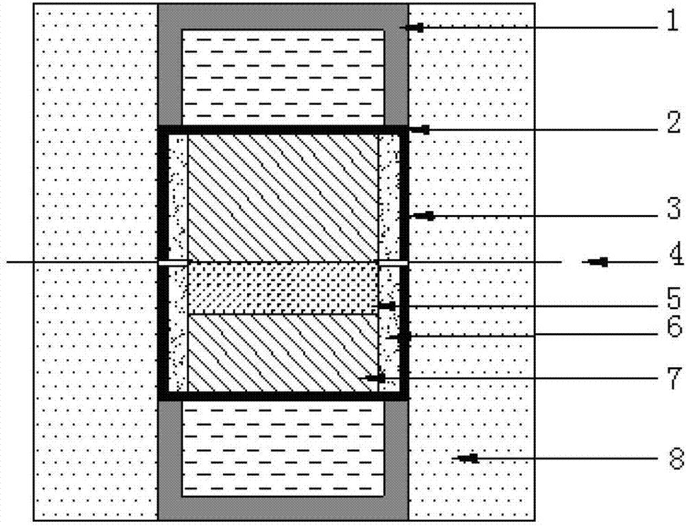
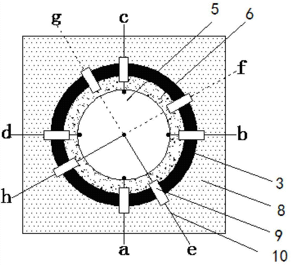
[0030] The structure of the device for in-situ testing of the transport properties of conductor substances under high temperature and high pressure is composed of figure 1 and figure 2 give. exist figure 1 and figure 2 Among them, 1 is a steel cap, 2 is a graphite sheet, 3 is a graphite tube, 4 is a copper wire (a total of 4 copper wires are counted as a, b, c, d), 5 is a sample, 6 is an MgO insulating tube, 7 is MgO insulating sheet, 8 is pyrophyllite block, 9 is ceramic tube, and 10 is thermocouple (two pairs of thermocouples can choose NiCr-NiAl thermocouple, e, h are the positive pole and negative pole of a pair of thermocouple f, g are another positive and negative terminals of a pair of thermocouples).

[0031] according to figure 1 , 2 As shown, the same as the assembly block synthesized by high temperature and high pressure, the side wall of the assembly block is composed of pyrophyllite block 8, graphite tube 3, and MgO insulating tube 6, and the two ends of t...

Embodiment 2

[0033] The assembly block synthesized by high pressure is according to the structure of embodiment 1 (ie figure 1 , 2 structure of the assembly block shown) was assembled and placed in the press. Connect the four side anvils with the DC power supply and the measuring instrument with wires. Set the pressure and temperature, start running, and start heating when the press reaches the set pressure. Wait for the temperature in the center of the cavity to be constant (generally after ten minutes of heating) to start resistivity measurement.

[0034] see figure 2 , current I ab Flow from a to b, and measure the voltage drop V at d and c dc , record the relative resistance value R A =V dc / I ab ; current I bc Flow from b to c, the voltage drop V is measured at a and d ad , record the relative resistance value R B =V ad / I bc . Then the relationship between sample resistivity ρ, sample thickness d and relative resistance value is:

[0035] exp(-πR A d / ρ)+exp(-π( B d / ...

Embodiment 3

[0037] The assembly block synthesized by high pressure is according to the structure of embodiment 1 (ie figure 1 , 2 The structure of the assembled block shown) was assembled and placed in a press in which the upper or lower surface of sample 5 passed through the center of the assembled block. Connect the four side anvils to the instrument for measuring potential difference with wires. After setting the pressure and temperature, start to run. When the press reaches the set pressure, it starts to heat. After heating for ten minutes, wait for the temperature in the center of the cavity to be constant, and start to measure the Seebeck coefficient.

[0038] see figure 2 , respectively measure the potential difference V between the positive poles of the two pairs of thermocouples ef and the potential difference between the negative electrode V hg ;according to the formula V ef =(S NiCr -S) ΔT,V hg =(S NiAl -S) ΔT, simultaneous: S=S NiAl -[V ef( S NiAl -S NiCr ) / (V ef...


PUM


Abstract

The invention discloses a device and a method for carrying out in-situ testing on the transport properties of conductor materials at high temperature and high pressure, and belongs to the field of high-pressure science and technologies and material science technologies. In the device, four copper wires (4) are introduced to a side face of a high-temperature and high-pressure synthetic assembling block and used as electrodes for measuring the resistivity, two pairs of thermocouples (10) are introduced for measuring seebeck coefficients, and welding points of a sample (5) and the electrodes as well as the sample (5) and the thermocouples (10) are fixed by using a pressure generated by a high-temperature and high-pressure device. The resistivity of the sample is calculated through measuring relative resistance values RA and RB and the thickness d of the sample subjected to pressurization; the seebeck coefficient of the sample is calculated through measuring a potential difference Vef between positive poles of the two pairs of thermocouples and a potential difference Vhg between negative poles of the two pairs of thermocouples. The method disclosed by the invention is simple, easy to implement, high in success rate, and good in experimental repetition rate; a problem that wires and the thermocouples are easy to fracture at the high pressure is solved; a situation that measured electrical signals are interfered by heating current is prevented, thereby ensuring the accuracy of results.

Description

technical field [0001] The present invention belongs to the field of high-voltage science and technology and material science and technology, and particularly relates to a kind of in-situ transport properties of conductor substances under high temperature and high pressure——electrical transport (conductivity) and heat transport (Seebeck coefficient) in-situ test technology. The purpose is to find high-performance thermoelectric materials and find out the working range with the best thermoelectric performance. Background technique [0002] Conductive substances increase in conductivity as pressure increases. Especially for semiconductor materials, the gap decreases with the increase of pressure, thereby enhancing its conductivity. In addition, the temperature effect also has a very important influence on the band gap of semiconductor materials. In general, the bandgap of semiconductor materials decreases with increasing temperature. In semiconductor materials, the potenti...

Claims


Application Information

Patent Timeline
Patent Type & Authority Applications(China)
IPC IPC(8): G01N27/04G01N27/00
Inventor 朱品文袁宝王欣张宇航崔田刘冰冰
Owner JILIN UNIV
Why Eureka
Try Eureka