
Dynamic gas lock

A dynamic gas lock and cylinder body technology, which is applied in the direction of microlithography exposure equipment, instruments, photoplate making process of pattern surface, etc., to achieve the effect of inhibiting the diffusion of impurities

Active Publication Date: 2013-11-20
INST OF MICROELECTRONICS CHINESE ACAD OF SCI
View PDF5 Cites 4 Cited by
  • Summary
  • Abstract
  • Description
  • Claims
  • Application Information

AI Technical Summary

Problems solved by technology

[0008] The technical problem to be solved by the present invention is how to better suppress the diffusion of extreme ultraviolet laser pollutants to the ultra-clean vacuum environment, and ensure that there will be no major loss when the extreme ultraviolet radiation passes through the dynamic gas lock

Method used


Image

  • Dynamic gas lock
  • Dynamic gas lock
  • Dynamic gas lock

Examples


Embodiment Construction

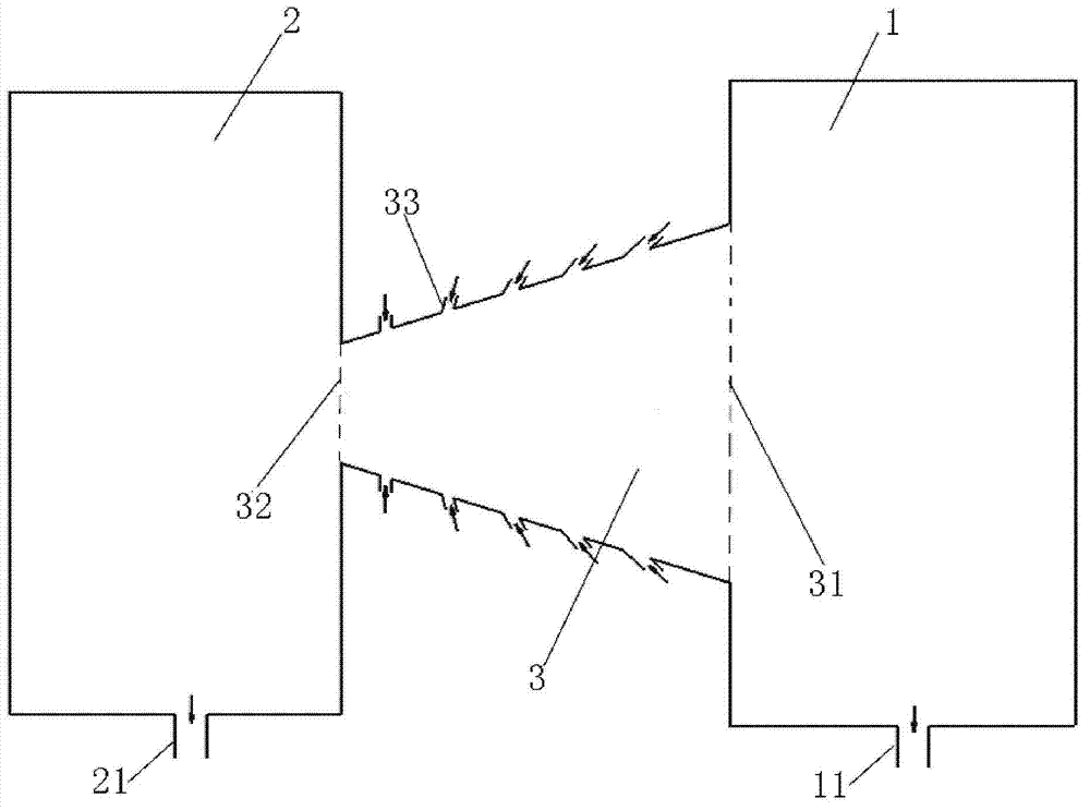
[0026] The dynamic gas lock proposed by the present invention presents a cylindrical shape, including a cylinder body with two ends open, the cylinder body has a wide mouth end and a narrow mouth end, the wide mouth end is connected with a first chamber, and the narrow mouth end is connected with a first chamber Two chambers.

[0027] The dynamic gas lock of the present invention is used to prevent substances in the second chamber from entering the first chamber. For example, the interior of the first chamber is an ultra-clean vacuum environment, and the interior of the second chamber is a clean vacuum environment. The present invention is used to prevent impurities and dust in the clean vacuum environment from entering the ultra-clean vacuum environment.

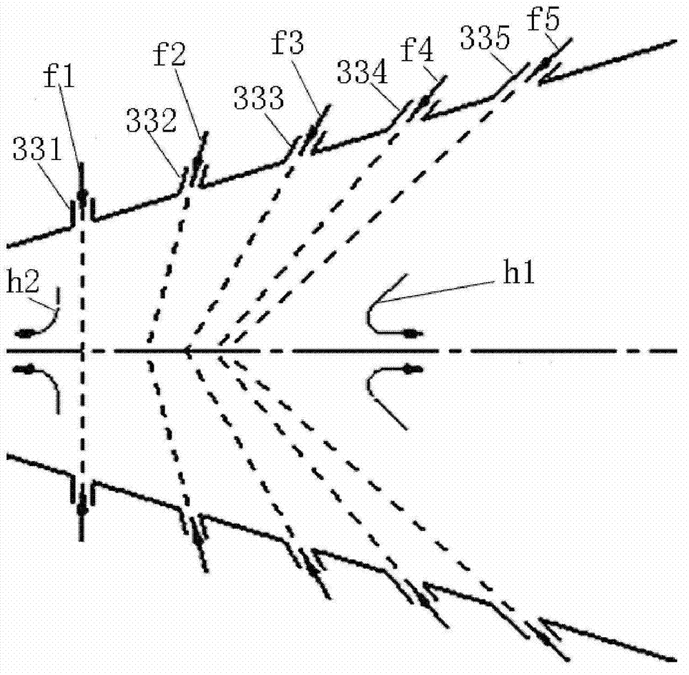
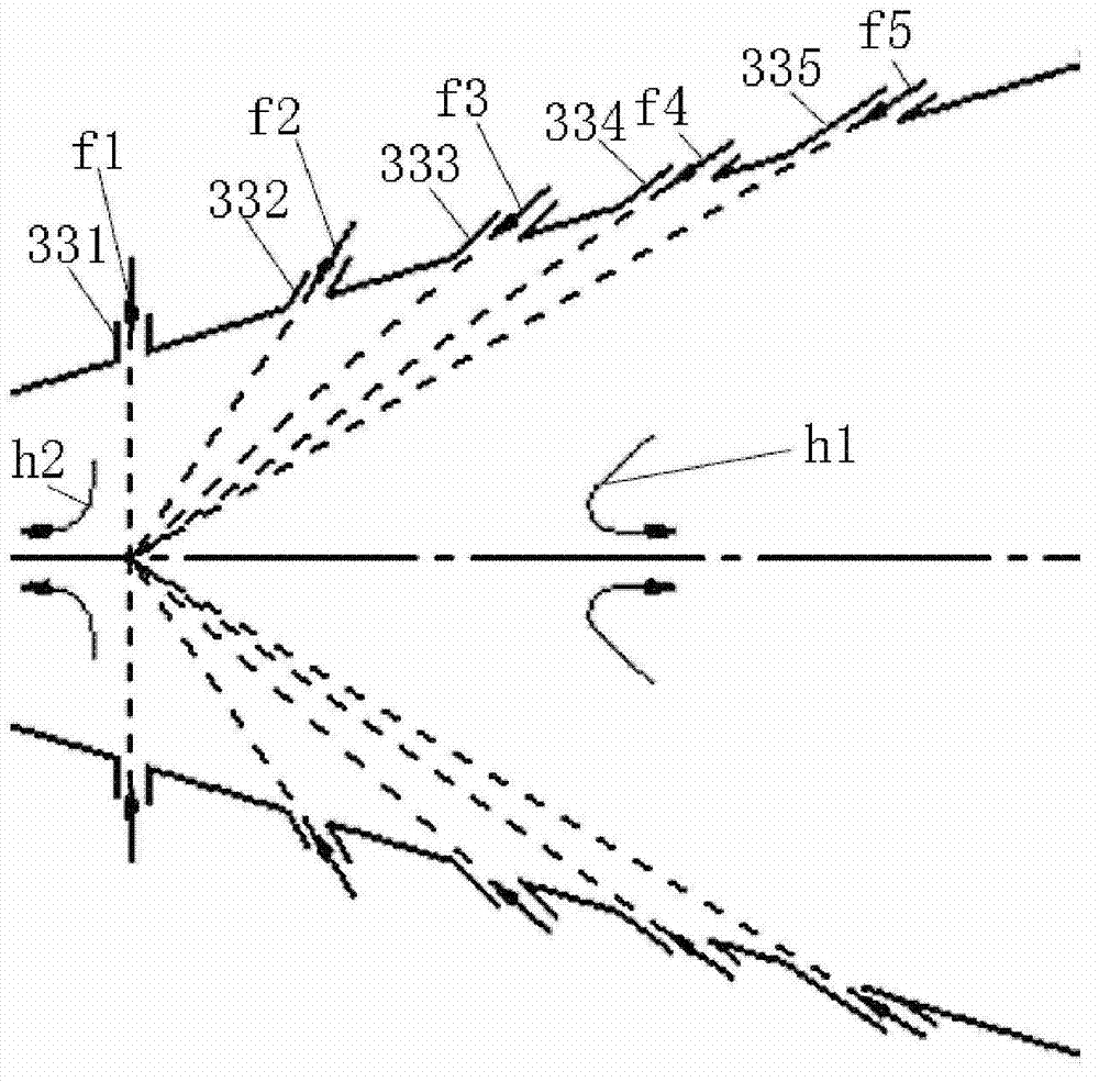
[0028] A plurality of nozzles are opened on the cylinder body of the cylindrical dynamic gas lock, and the plurality of nozzles all penetrate the side wall of the cylinder body, so as to blow a kind of gas to the inside of ...


PUM


Abstract

The invention discloses a dynamic gas lock, which is used for preventing a substance in a second chamber from entering in a first chamber. The dynamic gas lock comprises a barrel body with two open ends, wherein the barrel body is provided with a wide port end and a narrow port end, the wide port end is connected with the first chamber, and the narrow port end is connected with the second chamber; a plurality of nozzles are further formed in the barrel body, penetrate through the sidewall of the barrel body, and are used for blowing gas into the barrel body, and the airflow blown by each nozzle into the barrel body forms a sub-airflow; the central axis of each nozzle and the direction of the central axis of the barrel body extending to the wide port end form an acute angle or a right angle, and moreover, the angle formed by the central axis of the nozzle close to the wide port end and the central axis of the barrel body is not greater than the angle formed by the central axis of the nozzle close to the narrow port end and the central axis of the barrel body. The dynamic gas lock disclosed by the invention can be applied to an extreme-ultraviolet lithography machine, and the passage of extreme-ultraviolet irradiation through the dynamic gas lock with almost no loss is guaranteed better while impurity diffusion is suppressed.

Description

technical field [0001] The invention belongs to the technical field of extreme ultraviolet lasers, and in particular relates to a dynamic gas lock (Dynamic Gas Lock, DGL) for an extreme ultraviolet lithography machine (Extreme Ultraviolet Lithography, EUVL). Background technique [0002] Because air and almost all refractive optical materials have a strong absorption effect on extreme ultraviolet (EUV) radiation with a wavelength of 13.5nm, the EUV lithography machine is quite different from the lithography machine in an ordinary air environment. The main features of the extreme ultraviolet lithography machine are as follows: the optical system is a reflective optical system; the internal environment is a vacuum environment. In addition to having a high transmittance to 13.5nm EUV radiation, it must also be able to quickly discharge the generated pollutants. The light source, optical system, mask table and workpiece table of the extreme ultraviolet lithography machine are al...

Claims


Application Information

Patent Timeline
IPC IPC(8): G03F7/20
CPCG03F7/70916G03F7/70933
Inventor 陈进新王魁波王宇吴晓斌谢婉露张罗莎罗艳
Owner INST OF MICROELECTRONICS CHINESE ACAD OF SCI
Learn More