Large-scale user access oriented LR-PON layout planning method

A technology of LR-PON and passive optical network, which is applied in the field of fast heuristic search and solution of LR-PON network topology optimization, which can solve problems such as unpredictable engineering solution time, inability to effectively compensate losses, and large amount of engineering information processing , to achieve the effects of good scalability, good space flexibility, expansion scale and coverage

Inactive Publication Date: 2013-11-27
DALIAN MARITIME UNIVERSITY
View PDF2 Cites 7 Cited by
  • Summary
  • Abstract
  • Description
  • Claims
  • Application Information

AI Technical Summary

Problems solved by technology

[0004] The PON networking methods in the prior art only conduct independent modeling analysis for optical fiber transmission or network capacity, and cannot guarantee that the network coverage and optical network coverage can be effectively increased while large-scale users are connected to optical fibers at long distances. The capacity of the unit ONU, taking into account the transmission distance and network scale, cannot effectively compensate the loss caused by the signal during transmission when performing long-distance services in multi-user areas
On the other hand, the existing technology is generally optimized through optimization software after modeling. The amount of engineering information processing is large, and the computational complexity increases exponentially with the increase of network scale. Therefore, the requirements for computer hardware are strict, and the engineering solution time is not enough Estimation, and using modeling and mechanical optimization schemes, the optimization results often cannot be combined with the actual situation, and there are deviations between theory and reality

Method used


Image

  • Large-scale user access oriented LR-PON layout planning method
  • Large-scale user access oriented LR-PON layout planning method
  • Large-scale user access oriented LR-PON layout planning method

Examples


Embodiment

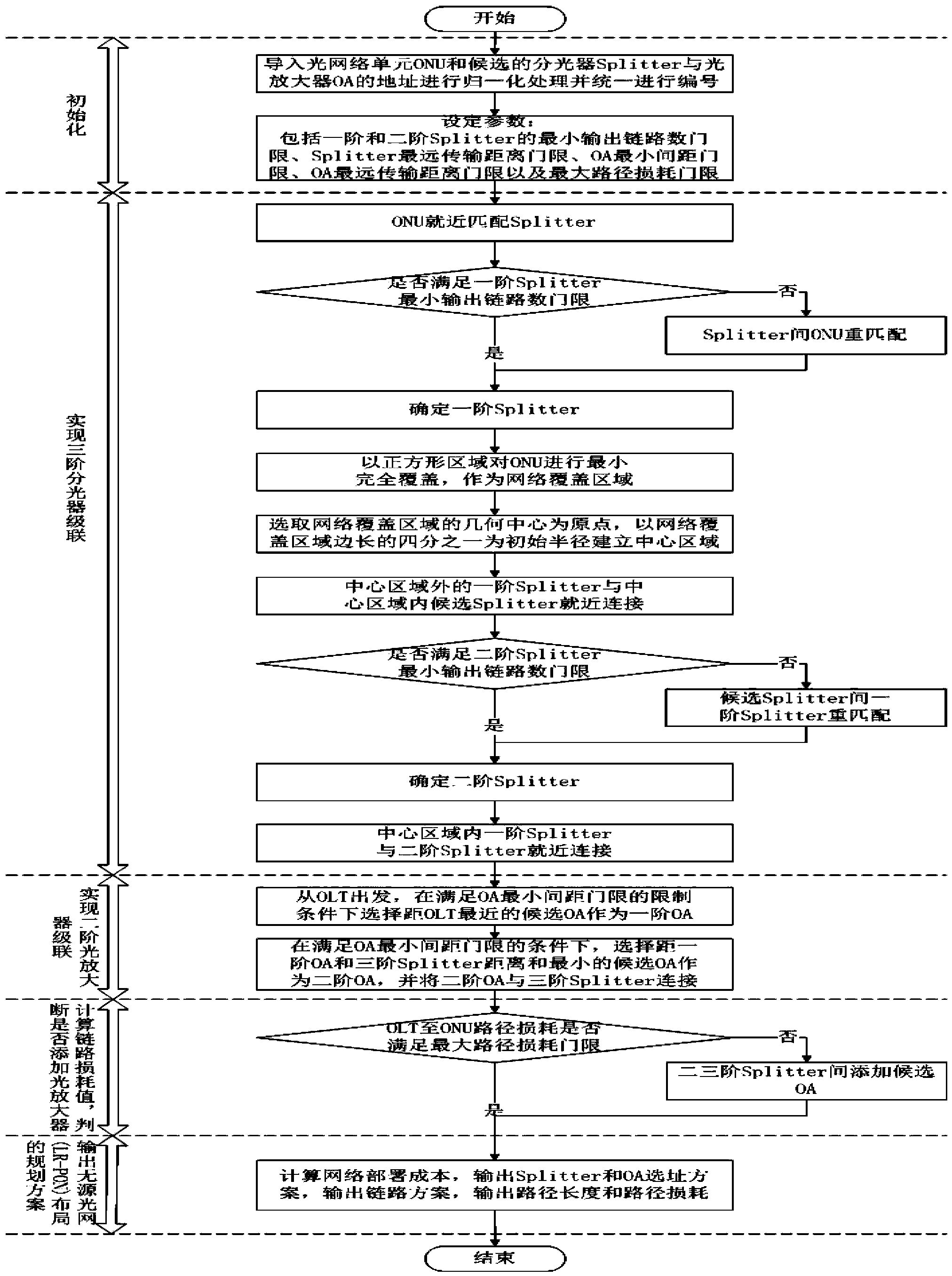
[0036] Such as figure 1 Shown: the LRPON layout planning method has the following steps:

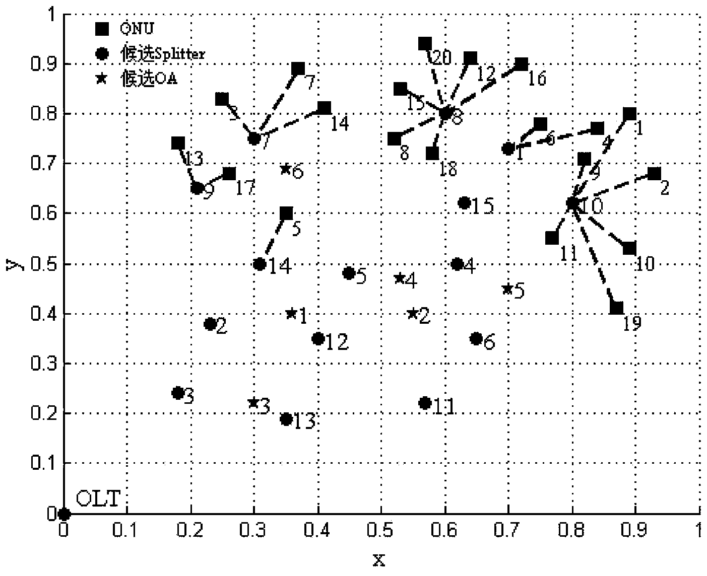
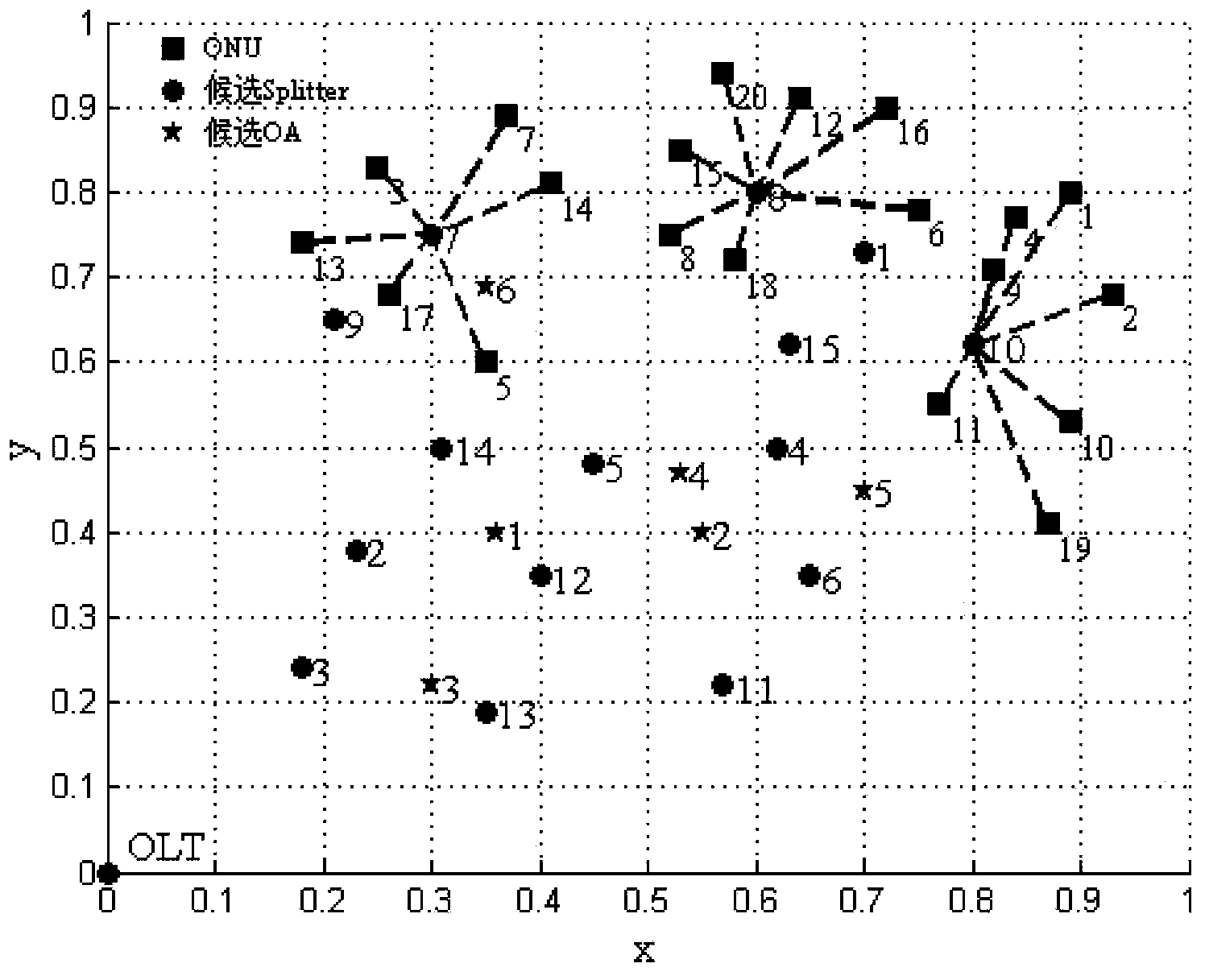
[0037] Step 1: Initialization: first select the target area through actual survey, set multiple optical network units, multiple candidate optical amplifiers OA and multiple candidate optical splitters in the target area, according to the actual latitude and longitude of their positions, use optical The line terminal OLT establishes a two-dimensional coordinate map as the origin. At this time, the optical network unit ONU, multiple candidate optical amplifiers OA, and multiple candidate optical splitters fall into the two-dimensional coordinate map according to their actual latitude and longitude positions. According to the order of optical network terminal OLT, candidate optical amplifier OA, candidate optical splitter and last optical network unit ONU, they are numbered in sequence, and the optical network unit ONU, candidate optical splitter and candidate optical amplifier OA are calcu...


PUM


Abstract

The invention discloses a large-scale user access oriented LR-PON layout planning method. In an LR-PON, a multi-order optical amplifier is brought in to carry out power compensation on an optical signal, so optical network coverage in a remoter distance and a larger range can be achieved. Network cost minimization serves as the purpose, connectedness of the whole network is guaranteed, and meanwhile, optical fiber coverage is carried out on the basis of an optical network unit, a plurality of candidate optical amplifiers and a plurality of candidate optical splitters. Compared with a traditional PON deployment method, the LR-PON layout planning method is oriented to large-scale user access; a three-stage cascade connection mode is adopted in a framework, a topological structure is ought to have good extendibility and space flexibility, therefore, more users are allowed to have access to the network, and the scale and the coverage range of the network are greatly expanded. Compared with a traditional mathematical modeling prioritization scheme, the LR-PON layout planning method reduces time complexity of calculation, therefore, greatly improves efficiency of engineering calculation, and effectively shortens calculation time.

Description

technical field [0001] The invention belongs to the field of optical fiber communication network, relates to the coverage planning problem of long-distance passive optical network (LR-PON), relates to a fast heuristic search and solution method for topology optimization of LR-PON network, and solves the layout planning of fast and flexible deployment of LR-PON question. Background technique [0002] Long Reach Passive Optical Network (LR-PON), as a next-generation PON technology, extends the transmission distance of traditional PON from 20km to 100km, and integrates optical access network and metropolitan area network into one system , can support larger-scale user access and longer-distance optical network coverage. Because it effectively avoids the electromagnetic interference of external equipment and the influence of lightning, it reduces the failure rate of lines and external equipment, improves the reliability of the system, makes the network construction faster, and ...

Claims


Application Information

Patent Timeline
Patent Type & Authority Applications(China)
IPC IPC(8): H04Q11/00
Inventor 林彬董杰
Owner DALIAN MARITIME UNIVERSITY
Why Eureka
Try Eureka