Turbine with moving blades with pits at blade tops

A technology of moving blades and turbines, which is applied to the supporting elements of blades, engine elements, machines/engines, etc., which can solve the problem of increasing the heat transfer coefficient of the local area of ​​the blade tip, increasing the unevenness of heat transfer at the blade tip, and ineffective control of gap leakage. It can achieve the effect of good applicability of attack angle change, reducing gap leakage and reducing rigidity

Active Publication Date: 2013-12-04
HARBIN ENG UNIV
View PDF6 Cites 18 Cited by
  • Summary
  • Abstract
  • Description
  • Claims
  • Application Information

AI Technical Summary

Problems solved by technology

[0002] Turbine blade tip clearance leakage flow is one of the most common flow phenomena in turbomachinery rotors. The lateral pressure difference on the blade tip surface causes leakage flow from the pressure surface to the suction surface. When the leakage flow flows out from the suction surface, it interacts with the main flow of the channel to form Leakage vortex, leakage flow and leakage vortex have a very important influence on turbine aerodynamic loss, heat transfer and unsteady downstream flow field: First, the leakage flow at the tip of the turbine blade produces a large aerodynamic loss. In the unshrouded turbine, The tip leakage loss can account for up to 45% of the rotor blade loss and 30% of the stage loss; secondly, the leakage flow and leakage vortex have a greater impact on the unsteadiness of the downstream flow field, which can cause blade structure vibration and noise, reduce reliability, and reduce engine life; finally, leakage flow and leakage vortex increase the complexity of heat transfer near the tip of the turbine blade. The effect causes the heat transfer coefficient of the blade tip to be greatly improved, and the leakage flow undergoes c

Method used


Image

  • Turbine with moving blades with pits at blade tops
  • Turbine with moving blades with pits at blade tops
  • Turbine with moving blades with pits at blade tops

Examples


Embodiment approach 1

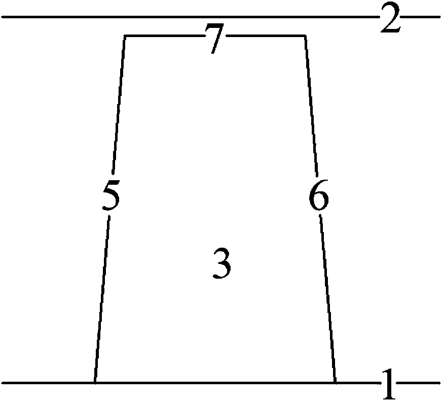
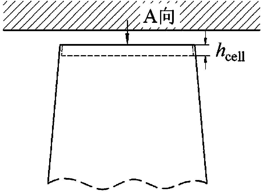
[0021] With reference to Figures 2 to 3, to manufacture the turbine blades with holes on the tip of the present invention, the gas turbine blades are first designed by traditional design methods. For a given blade load distribution and operating conditions, the specific structural parameters of the tip honeycomb (the honeycomb core size d cell And honeycomb depth h cell ) Can be obtained by simulation or experiment with existing computational fluid dynamics software, and then the honeycomb structure as shown in Figure 3(a) is processed on the tip surface of the blade. The ratio of the honeycomb core cell size to the maximum thickness of the blade tip is 0.1-0.5, the ratio of the honeycomb depth to the maximum thickness of the blade tip is 0.1-0.5, and the honeycomb depth is not less than the size of the honeycomb core cell. Those skilled in the art should understand that for turbine blades for specific applications, the honeycomb structure parameters of the blade tip are selecte...

Embodiment approach 2

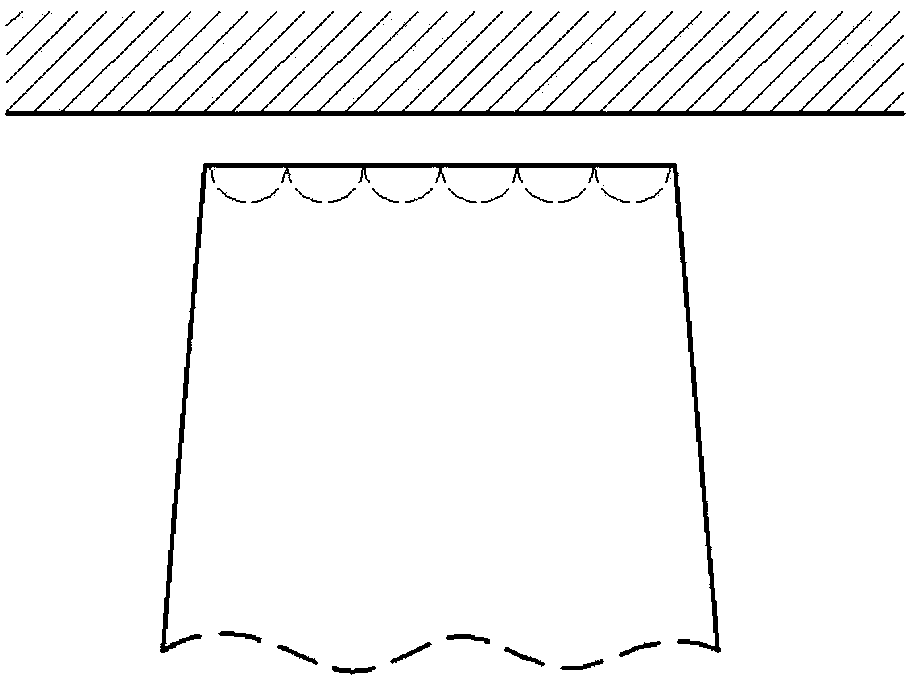
[0026] Such as Figure 3c , Figure 3d As shown, the shape of the tip hole is a ball socket, and the ratio of the diameter of the ball socket to the maximum thickness of the tip is 0.1-0.5, and the others are the same as in Embodiment 1.


PUM


Abstract

The invention aims at providing a turbine with moving blades with pits at blade tops. The turbine comprises a case and a hub. The moving blades are uniformly installed along the circumferential direction of the hub. The hub and the moving blades are installed in the case. The pits are arranged at the blade tops of the moving blades. By designing the turbine blades with the pits at the blade tops, on one hand, the clearance leakage amount is reduced, the turbine efficiency is improved and the attack angle change applicability is good; on the other hand, the heat load on the surfaces of the blade tops and the heat transfer coefficient of local areas of the blade tops are reduced, the non-uniform extent of heat transfer of the blade tops is reduced and the service life of the blades is improved; the weight of the ends of the blade tops can be reduced, the rigidity produced when the blades rub the case is reduced and the working reliability of the gas turbine is improved.

Description

Technical field [0001] The invention relates to a turbine, in particular to turbines of aero engines and gas turbines. Background technique [0002] Turbine tip clearance leakage flow is one of the most common flow phenomena in impeller machinery rotors. The transverse pressure difference on the tip surface causes leakage flow from the pressure surface to the suction surface. When the leakage flow flows out from the suction surface, it interacts with the main flow of the channel. Leakage vortex, leakage flow and leakage vortex have a very important impact on the aerodynamic loss, heat transfer and unsteadyness of the downstream flow field of the turbine: First, the leakage flow at the tip of the turbine blade produces a large aerodynamic loss. In a turbine without a crown, The top leakage loss can account for up to 45% of the rotor loss and 30% of the stage loss respectively; secondly, the leakage flow and leakage vortex have a greater impact on the unsteadyness of the downstream...

Claims


Application Information

Patent Timeline
IPC IPC(8): F01D11/08F01D5/14
Inventor 高杰郑群姜斌张正一
Owner HARBIN ENG UNIV
Why Eureka
Try Eureka