Dispensing device container filled with liquid curable composition, manufacturing method thereof, and dispensing device

A technology of curable composition and manufacturing method, which is applied in the fields of devices for coating liquid on the surface, semiconductor/solid-state device manufacturing, lighting devices, etc., and can solve problems such as the influence of liquid curable composition properties, generation of bubbles, and increase in viscosity , to achieve excellent storage stability and prevent air bubbles

Active Publication Date: 2016-11-16
KANEKA CORP
View PDF33 Cites 0 Cited by
  • Summary
  • Abstract
  • Description
  • Claims
  • Application Information

AI Technical Summary

Problems solved by technology

[0009] However, especially when the liquid curable composition is used in large quantities, Figure 11 In the case of the spraying device shown, since the pressurized fluid comes into contact with the liquid curable composition A in the pressurized container 46, air bubbles may be entrapped in the liquid curable composition A, and the liquid curable composition A may be coated on the cover plate. Air bubbles are generated in the liquid curable composition or the cured product after waiting for part 40
In addition, depending on the type of liquid curable composition, the characteristics of the liquid curable composition may be affected by contact with pressurized fluid.
For example, in the case of using a moisture-curable composition as a liquid-curable composition, there is a concern that solidification may occur when the liquid is fed from the tank to the nozzle unless the pressurized fluid is used to sufficiently remove the wet water. problems such as increased viscosity
[0010] In addition, especially in the case of using a closed syringe, the above-mentioned problems can be avoided, but there is a problem that it is limited to a small amount of use and cannot be used in large quantities.

Method used


Image

  • Dispensing device container filled with liquid curable composition, manufacturing method thereof, and dispensing device
  • Dispensing device container filled with liquid curable composition, manufacturing method thereof, and dispensing device
  • Dispensing device container filled with liquid curable composition, manufacturing method thereof, and dispensing device

Examples


Embodiment

[0416] The present invention will be described in more detail below with reference to specific examples, but the present invention is not limited to the following examples.

[0417] In addition, in the following examples, "number average molecular weight" and "molecular weight distribution (ratio of weight average molecular weight to number average molecular weight)" were calculated by the standard polystyrene conversion method using gel permeation chromatography (GPC). However, a column packed with polystyrene cross-linked gel was used as a GPC column (shodex GPC K-804 and K-802.5; manufactured by Showa Denko Co., Ltd.), and chloroform was used as a GPC solvent.

[0418] 1 ASX-400 (400 MHz) manufactured by Bruker Co., Ltd. was used for H-NMR, and it measured at 23 degreeC using heavy chloroform as a solvent.

[0419] In the following examples, the "average number of terminal crosslinkable silyl groups or (meth)acryloyl groups" is "the number of crosslinkable silyl groups and...

manufacture example 1、2

[0423] The amount of each raw material used is shown in Table 1.

[0424] (1) Polymerization process

[0425] Acrylates (premixed acrylates) were deoxygenated. The inside of the stainless steel reaction container with a stirrer was deoxidized, and part of cuprous bromide and all acrylates (in Table 1, the monomer charged initially) was charged, and heated and stirred. Add and mix acetonitrile (recorded as acetonitrile for polymerization in Table 1), diethyl 2,5-dibromoadipate (DBAE) or ethyl 2-bromobutyrate as initiator, at the temperature of the mixture When the temperature was adjusted to about 80° C., pentamethyldiethylenetriamine (hereinafter, simply referred to as triamine) was added to start the polymerization reaction. The remaining acrylates (referred to as additional monomers in Table 1) were gradually added to perform a polymerization reaction. During the polymerization, a triamine is appropriately added to adjust the polymerization rate. The total amount of tria...

manufacture example 3

[0440] The amount of each raw material used is shown in Table 2.

[0441] (1) Polymerization process

[0442] Deoxygenation of acrylates (in the case of copolymerization, premixed with a given amount of acrylates) is carried out. The inside of the stainless steel reaction container with a stirrer was deoxidized, and part of cuprous bromide and all acrylates (in Table 2, the monomer charged initially) was charged, and heated and stirred. Add and mix acetonitrile (referred to as acetonitrile for polymerization in Table 2), diethyl 2,5-dibromoadipate (DBAE) as an initiator, and add pentaform when the temperature of the mixture is adjusted to about 80°C Diethylenetriamine (hereinafter referred to simply as triamine) to start the polymerization reaction. The remaining acrylate (referred to as an additional monomer in Table 2) was gradually added to perform polymerization reaction. During the polymerization, a triamine is appropriately added to adjust the polymerization rate. The ...


PUM


Abstract

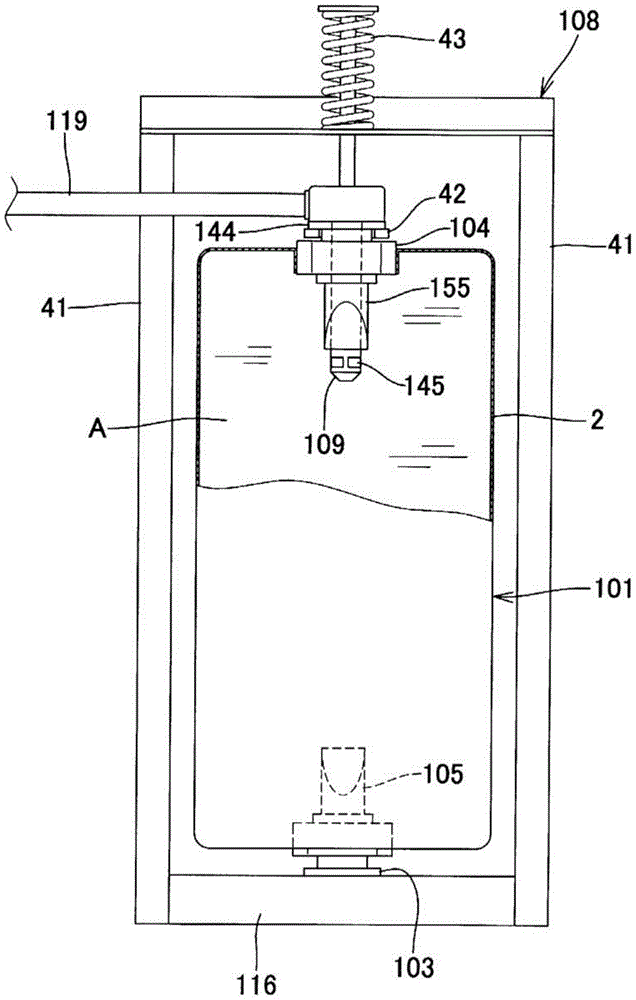
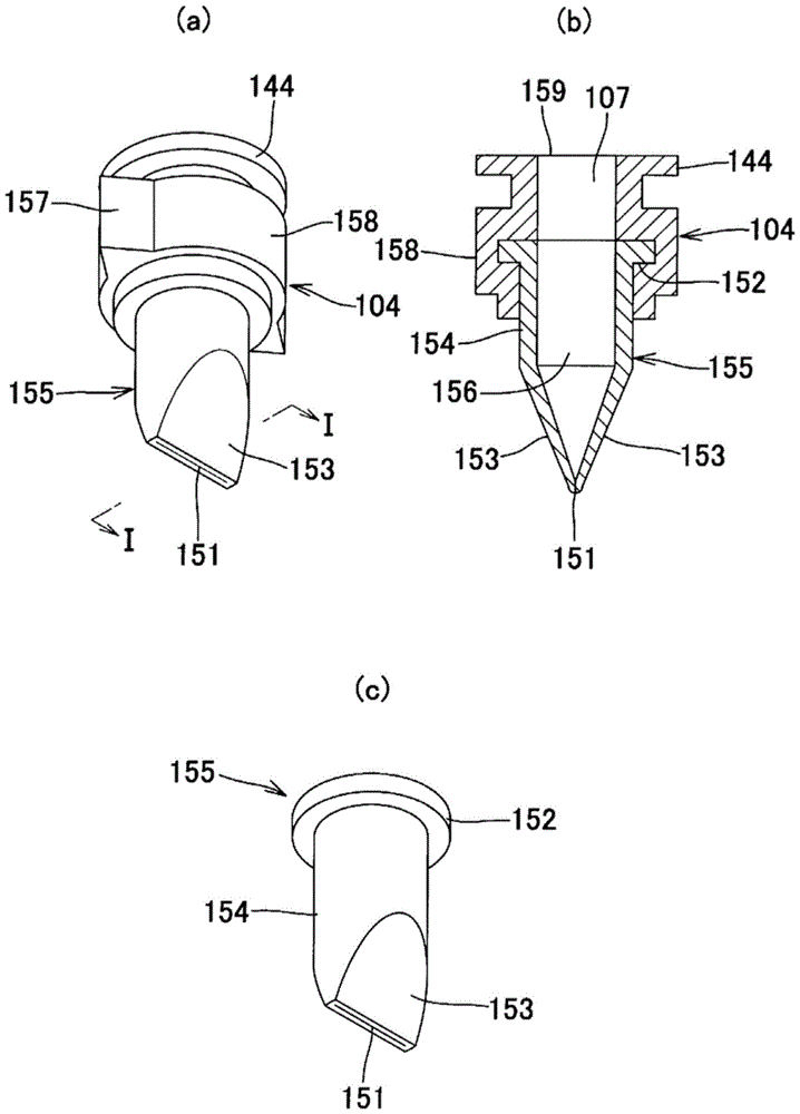
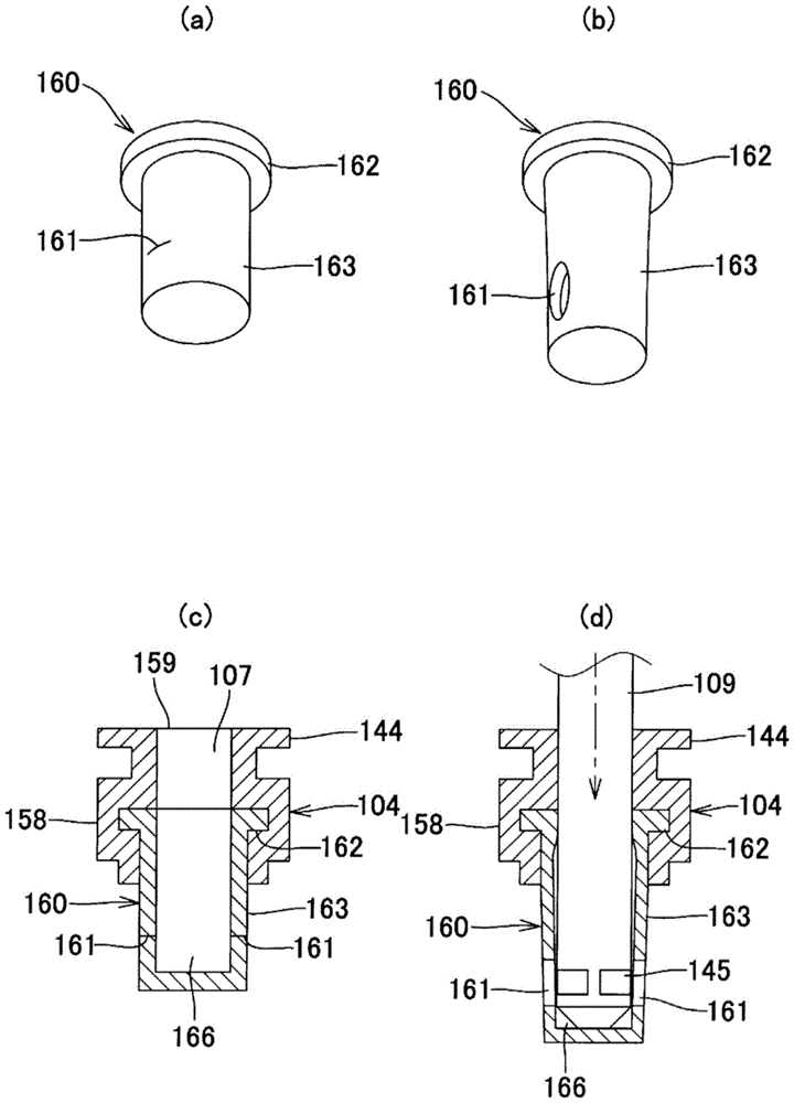
The object of the present invention is to provide a container (101) for a discharge device filled with a liquid curable composition (A), which is suitable for mass production, has excellent storage stability, and does not require defoaming treatment during use. It can prevent the generation of air bubbles during coating and after curing. The container (101) for the discharge device filled with the liquid curable composition (A) can be deformed by the extrusion force from the outside, and is equipped with a discharge device (C) that can be connected to the discharge device (C) on one end side in the longitudinal direction. The discharge-side connection part (104) and the discharge-side seal part (155) capable of opening and closing the discharge-side connection part (104) are equipped with a function different from the discharge-side connection part (104). The filling-side connecting portion (103) filled with the liquid curable composition (A) in an airtight state and the filling-side sealing portion (105) capable of opening and closing freely sealing the filling-side connecting portion (103) are filled with the liquid curable composition (A). The container (101) for a spraying device of the active composition (A) can achieve the above object.

Description

technical field [0001] The present invention relates to a container for a discharge device filled with a liquid curable composition filled between a protective member and a display module of various display devices, and a method for producing the same. The present invention also relates to a dispensing device using the container for a dispensing device filled with such a liquid curable composition. Background technique [0002] Used in various display devices such as liquid crystal type touch panels, organic type EL touch panels, liquid crystal modules, plasma display panels (PDP), digital and analog speedometers mounted in electrical or electronic equipment and two-wheeled or four-wheeled vehicles In some cases, gaps (gap) are formed between the protective member of the display part (hereinafter, sometimes referred to as a cover plate.) and the display module, so there are problems in impact resistance and visibility. [0003] As a countermeasure, for example, for touch-pa...

Claims


Application Information

Patent Timeline
Patent Type & Authority Patents(China)
IPC IPC(8): B05C11/10H01L51/50H05B33/04H05B33/10
CPCB05C11/10B05C5/0216B05C11/1002H05B33/04H05B33/10H10K50/00
Inventor 石川豪生大内学玉井仁
Owner KANEKA CORP
Why Eureka
Try Eureka