Gain and slew rate enhancement type amplifier

A technology of slew rate enhancement and amplifier, which is applied in differential amplifiers, improved amplifiers to expand bandwidth, and DC-coupled DC amplifiers. The effect of performance and slew rate improvement

Active Publication Date: 2013-12-18
NO 24 RES INST OF CETC
View PDF3 Cites 19 Cited by
  • Summary
  • Abstract
  • Description
  • Claims
  • Application Information

AI Technical Summary

Problems solved by technology

[0004] In order to overcome the above-mentioned problems of low gain and slew rate of the conventional current mirror transconductance amplifier, the present invention proposes a gain and slew rate enhanced amplifier, which only needs to add a small number of devices, and can be used without significantly increasing the power consumption of the circuit. Dramatically boost amplifier gain and slew rate

Method used


Image

  • Gain and slew rate enhancement type amplifier
  • Gain and slew rate enhancement type amplifier
  • Gain and slew rate enhancement type amplifier

Examples


Embodiment Construction

[0020] The specific implementation manners of the present invention are not limited to the following description, and are now further described in conjunction with the accompanying drawings.

[0021] The circuit diagram of a gain and slew rate enhanced amplifier of the present invention is as figure 2 As shown, it is composed of a differential input stage and a double-ended-to-single-ended unit. Its specific structure, connection relationship, and functional relationship are the same as the content of the invention in this specification, and will not be repeated here. Among them, A, B, C and D represent the current ratio of each branch. It works like this:

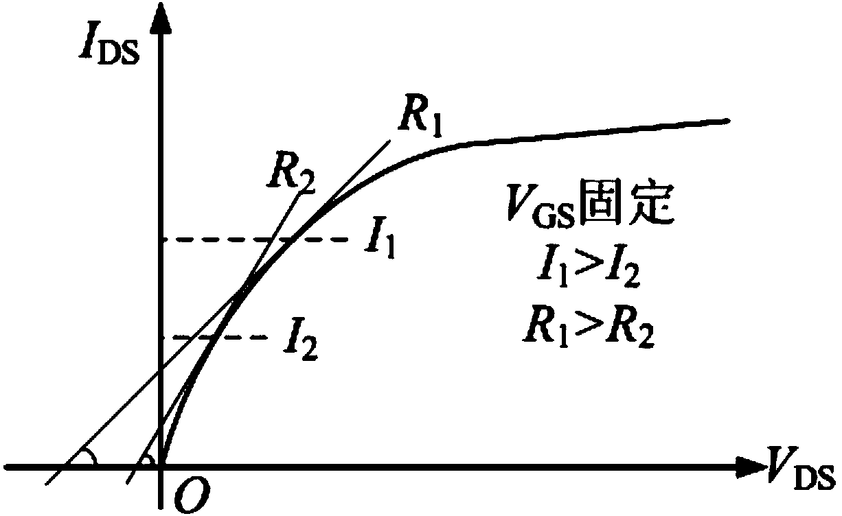
[0022] First analyze the static working situation. Transistor M A1 , M A2 , M B1 and M B2 The gate bias voltage is V BN , which is in the deep linear region during static operation and acts as a small resistor. When the current is small, its influence on the current mirror can be ignored; when the current increase...


PUM


Abstract

The invention relates to a gain and slew rate enhancement type amplifier, which is realized by a current mirror type operational transconductance amplifier (OTA). The gain and slew rate enhancement type amplifier consists of a differential input stage unit and a double-end to single-end unit. The amplifier disclosed by the invention adopts a mode of adding current control variable resistors to optimize a current mirror structure, and a circuit can obtain higher voltage gain and bandwidth under the situation of the same static power consumption. During big-signal inputting, a higher slew rate can be obtained. According to the gain and slew rate enhancement type amplifier disclosed by the invention, by only adding four current control variable resistors, the circuit slew rate is improved to 4.8V / mu s from 0.88V / mu s and the band width is improved to 4.3MHz from 2.54MHz on the premise that the amplifier keeps the same power consumption. The circuit disclosed by the invention can be widely applied to the circuit fields such as a switched capacitor circuit, a data converter and a mixed signal system on chip.

Description

technical field [0001] The invention relates to an amplifier, in particular to a gain and slew rate enhanced amplifier, which is applied to the field of integrated circuits such as switched capacitor circuits, data converters, and mixed-signal on-chip systems. Background technique [0002] High-performance operational transconductance amplifier (OTA) is an important part of analog circuits such as switched capacitor filters, power management, and data converters. It is also a basic module for more complex and highly integrated mixed-signal SoCs. In most applications, transconductance amplifiers must meet requirements such as wide bandwidth, high gain, enhanced slew rate, and low power consumption. [0003] The current mirror transconductance amplifier is a common implementation in the industry because it has only a single pole, is stable without frequency compensation, and has a wide output swing for ease of design. Document 1 (JeongJin Roh, High-Gain Class-AB OTA with Low ...

Claims


Application Information

Patent Timeline
Patent Type & Authority Applications(China)
IPC IPC(8): H03F3/45H03F1/42
Inventor 黄晓宗石建刚刘伦才王健安黄文刚
Owner NO 24 RES INST OF CETC
Why Eureka
Try Eureka