A fluidized bed device for preparing aromatics from alkanes and its preparation method

A fluidized bed, aromatics technology, applied in chemical instruments and methods, chemical recovery, organic chemistry, etc., can solve the problems of difficult to improve conversion rate and aromatics yield, low process driving force, influence of heating tube strength, etc. Increase independence and operational flexibility, reduce equipment costs, and reduce the effect of heating pipe area

Active Publication Date: 2015-10-28
TSINGHUA UNIV +1
View PDF3 Cites 0 Cited by
  • Summary
  • Abstract
  • Description
  • Claims
  • Application Information

AI Technical Summary

Problems solved by technology

At the same time, the gas-solid backmixing in the single-stage fluidized bed reactor is serious
For recalcitrant propane and / or butane, or propane and / or butane with C 5 -C 7 For non-aromatic mixtures, the process driving force is not high, the conversion rate and aromatics yield are not easy to increase, the amount of raw materials that need to be recycled increases, and the process energy consumption is high.
Moreover, although the heating tube has been used to supply heat to different systems under high temperature conditions, the strength of the heating tube under high temperature conditions will be affected due to the presence of a large number of moving particles in the fluidized bed reactor.
Therefore, the heating tube of the fluidized bed reactor should neither be too long nor too many, resulting in limited heating capacity

Method used


Image

  • A fluidized bed device for preparing aromatics from alkanes and its preparation method
  • A fluidized bed device for preparing aromatics from alkanes and its preparation method
  • A fluidized bed device for preparing aromatics from alkanes and its preparation method

Examples


Embodiment 1

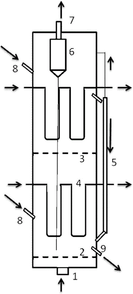
[0041] For a two-stage fluidized bed device as shown in Figure 1, the distance between the upper outlet of the outer overflow pipe and the adjacent lower distribution plate is 0.1 times the diameter of the device. The inlet of the lower part of the outer overflow pipe is located in the first layer of catalyst bed. The two catalyst inlets lead into two catalyst beds respectively, and the position of the catalyst inlet in the second catalyst bed is 0.4m higher than the upper outlet of the overflow pipe outside the device. The gas contained in the catalyst entering from the upper outlet of the outer overflow pipe is led to the vicinity of the catalyst recovery system in the device through the pipeline. The cross-sectional area of ​​the set finned heating tube accounts for 20% of the radial cross-sectional area of ​​the device.

[0042] While passing air at 600°C from the gas inlet 1 through the gas distributor 2, the fluidized catalyst is loaded into the device from the catalyst i...

Embodiment 2

[0046] For a two-stage fluidized bed device as shown in Figure 1, the distance between the upper outlet of the outer overflow pipe 5 and the adjacent lower distribution plate is 1 times the diameter of the device. The lower inlet of the outer overflow pipe is located in the first catalyst bed. The two catalyst inlets lead into two catalyst beds respectively, and the position of the catalyst inlet 8 in the second catalyst bed is 1.5m higher than the upper outlet of the outer overflow pipe 5 outside the device. The gas contained in the catalyst entering from the upper outlet of the outer overflow pipe is led to the vicinity of the catalyst recovery system 6 in the device through pipelines. The cross-sectional area of ​​the set finned heating tube accounts for 35% of the radial cross-sectional area of ​​the device.

[0047] While the air at 300°C is introduced from the gas inlet of the device through the gas distributor, the fluidized catalyst is loaded into the device from the ...

Embodiment 3

[0051] For a two-stage fluidized bed device as shown in Figure 1, the distance between the upper outlet of the outer overflow pipe and the adjacent lower distribution plate is twice the diameter of the device. The lower inlet of the outer overflow pipe is located in the first catalyst bed. The two catalyst inlets lead into two catalyst beds respectively, and the position of the catalyst inlet in the second catalyst bed is 1m higher than the upper outlet of the overflow pipe outside the device. The gas contained in the catalyst entering from the upper outlet of the outer overflow pipe is led to the vicinity of the catalyst recovery system in the device through the pipeline. The cross-sectional area of ​​the set finned heating tube accounts for 25% of the radial cross-sectional area of ​​the device.

[0052] While nitrogen gas at 600°C is introduced from the gas inlet through the gas distributor, the fluidized catalyst is loaded into the device from the catalyst inlet. The main...


PUM

PropertyMeasurementUnit
diameteraaaaaaaaaa
densityaaaaaaaaaa
diameteraaaaaaaaaa

Abstract

The invention discloses a fluidized bed device and a preparation method for preparing aromatic hydrocarbon from alkyl hydrocarbon. The device comprises a gas inlet, a gas outlet, a gas distributor and a catalyst recovering system, and also comprises a distributing plate, a heating pipe, an outer overflow pipe, a catalyst inlet and a deactivated catalyst outlet, wherein the distributing plate is arranged transversely in the device, the heating pipe is arranged above and below the distributing plate, the inlet and the outlet of the heating pipe are connected to the inner wall of the device, the opening of the lower part of the outer overflow pipe is connected to the lowermost catalyst bed layer, the upper part of the outer overflow pipe is parallel to the vertical direction of the device, the lower part of the catalyst inlet is connected to the left side wall of the device and the upper part of the outer overflow pipe protrudes tipsily and upwards from the left side wall of the device, the upper part of the deactivated catalyst outlet is connected to the right side wall of the device and the lower part of the deactivated catalyst outlet protrudes tipsily and downwards from the right side wall of the device. The preparation method comprises the steps of: introducing gas while adding a catalyst, electrifying or adding a medium into the heating pipe, feeding the raw material gas, separating a gas product from the catalyst, recovering the catalyst, obtaining the gas product, regenerating the catalyst, and successively repeating the processes.

Description

technical field [0001] The invention belongs to the technical field of chemical industry, and in particular relates to a fluidized bed device and a method for preparing aromatics from alkanes. Background technique [0002] Aromatics are one of the important basic chemicals. In traditional chemical preparation, aromatics are mainly obtained through petroleum refining and coal dry distillation. Aromatics obtained from petroleum are of high purity and are suitable for the preparation of various high-quality chemicals. The aromatics obtained by coal dry distillation are of relatively low quality due to thiophene impurities, and their application is limited. With the increasing shortage of petroleum resources, the supply of aromatics is tense, and the price remains high, which greatly increases the production cost of subsequent chemicals and affects their sales. The technology of converting raw materials such as methane, liquefied gas or methanol into aromatics can form a benef...

Claims


Application Information

Patent Timeline
Patent Type & Authority Patents(China)
IPC IPC(8): B01J8/24C07C15/00
CPCY02P20/584
Inventor 骞伟中汤效平魏飞王彤崔宇高长平黄晓凡丁焕德
Owner TSINGHUA UNIV
Why Eureka
Try Eureka