Hydraulic device of water turbine speed governing and protection system
A technology of hydraulic device and protection system, applied in the field of hydraulic device, can solve the problems of large oil demand, large valve body size, difficult quality control, etc., to achieve the effect of improving adjustment quality, reliable operation and saving space
- Summary
- Abstract
- Description
- Claims
- Application Information
AI Technical Summary
Problems solved by technology
Method used
Image

Examples
Embodiment Construction
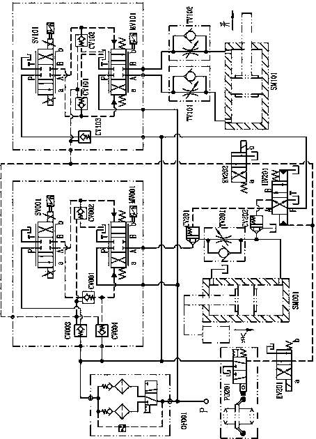
[0034] Such as Figure 1-9As shown, the present invention is a hydraulic device for hydraulic turbine speed regulation and protection system, including guide vane control valve group 2 and vane control valve group 3 connected with pressure oil source P, guide vane control valve group 2 and vane control valve group The valve group 3 is connected to the guide vane servomotor SM001 and the vane servomotor SM101 respectively. The innovation of the hydraulic device of the hydraulic turbine speed regulation and protection system of the present invention is that it also includes an emergency shutdown circuit and a shutdown control valve group. The emergency shutdown circuit is connected in series between the guide vane control valve group 2 and the guide vane servomotor SM001. Shutdown control valve group includes pure mechanical hydraulic overspeed protection device PD201 and emergency / accident shutdown hydraulic control valve group 4. The purely mechanical hydraulic overspeed pro...
PUM
 Abstract
Description
Claims
Application Information
 - Generate Ideas
- Intellectual Property
- Life Sciences
- Materials
- Tech Scout
- Unparalleled Data Quality
- Higher Quality Content
- 60% Fewer Hallucinations
Browse by: Latest US Patents, China's latest patents, Technical Efficacy Thesaurus, Application Domain, Technology Topic, Popular Technical Reports.
© 2025 PatSnap. All rights reserved.Legal|Privacy policy|Modern Slavery Act Transparency Statement|Sitemap|About US| Contact US: help@patsnap.com