Biomass fuel aluminum melting furnace

A biomass fuel and aluminum melting furnace technology, applied in the field of aluminum melting furnaces, can solve the problems of poor heat preservation performance, high fuel consumption, high cost, etc., to enhance the ability to maintain the temperature in the crucible, delay the loss of room temperature, and reduce consumption costs Effect

Inactive Publication Date: 2013-12-25
HUZHOU YUANTE NEW MATERIALS
View PDF7 Cites 12 Cited by
  • Summary
  • Abstract
  • Description
  • Claims
  • Application Information

AI Technical Summary

Problems solved by technology

[0002] Aluminum melting furnaces are usually furnaces heated by burning fossil fuels, such as coke furnaces, oil furnaces, or furnaces heated by electricity, such as electric melting furnaces. Aluminum melting furnaces heated by burning solid biomass fuels are called biomass fuel aluminum melting furnaces , the prior art biomass fuel aluminum melting furnace follows the structure of the coke furnace, and has poor thermal insulation performance. In addition, the biomass fuel burns rapidly and lacks continuous embers heat. A large amount of heat is lost through the flue to maintain the melting temperature of the aluminum alloy in the crucible. Insufficient capacity, in order to maintain the temperature in the furnace, the feeding material must be continuously burned, resulting in large fuel consumption and high cost of melting aluminum. Therefore, the existing technology has the problems and deficiencies of large energy consumption and high cost

Method used


Image

  • Biomass fuel aluminum melting furnace
  • Biomass fuel aluminum melting furnace

Examples


Embodiment Construction

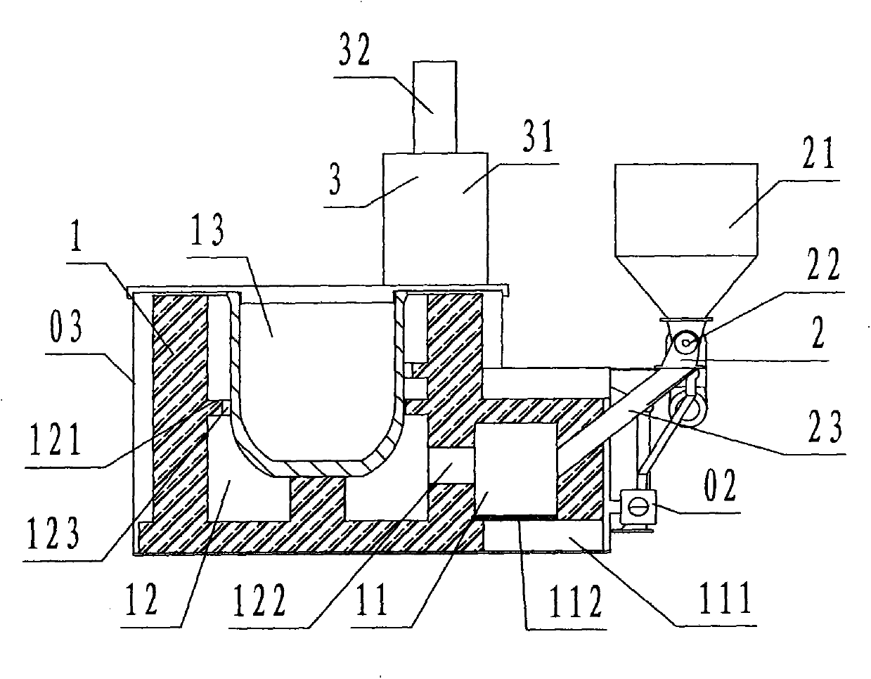
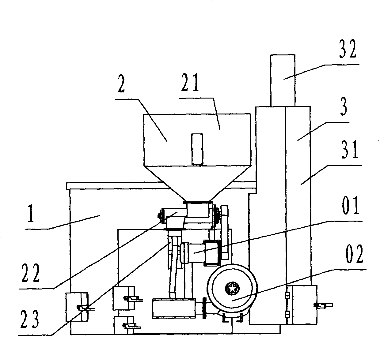
[0018] refer to figure 1 , figure 2 , a biomass fuel aluminum melting furnace of the present invention comprises a furnace body 1, a screw feeder 2, and a chimney 3, and the furnace body 1 is made of a refractory material composed of a combustion chamber 11, a heating chamber 12 and a crucible 13. The device, wherein, the heating chamber 12 is located at the left part of the furnace body 1, the heating chamber 12 is hollow, the upper part is open, the lower part has a bottom, and the cylindrical barrel-shaped structure, the crucible 13 is located in the heating chamber 12, and the heating chamber 12 furnace wall A horizontal ring-shaped partition wall is set between the outer wall of the crucible 13 and is called a fire barrier layer 121, and several rectangular gaps are evenly distributed on the inner circle of the fire barrier layer 121 in contact with the crucible 13, which are called hot gas. Road 123; the upper edge of the crucible 13 is flush with the upper edge of the...


PUM


Abstract

The invention discloses a biomass fuel aluminum melting furnace. The biomass fuel aluminum melting furnace comprises a furnace body (1), a screw feeding machine (2) and a chimney (3). The furnace body is composed of a combustion chamber, a heating chamber and a crucible, and the crucible is arranged inside the heating chamber; a flame baffle layer and a hot air duct are arranged between the furnace wall of the heating chamber and the crucible; the chimney is communicated with the heating chamber; the fuel chute of the screw feeding machine is communicated with the combustion chamber. when the biomass fuel aluminum melting furnace works, solid biomass fuel is pushed into the combustion chamber by the screw feeding machine for combustion, flame generated through the combustion enters the heating chamber through a flame vent and heats the crucible around the outer wall of the crucible front bottom to top through the hot air vent under the action of the flame baffle layer, and smoke is exhausted to the atmosphere through the chimney. According to the technical scheme of the biomass fuel aluminum melting furnace, through the flow retarding function of the flame baffle layer, heat exchange is enhanced, temperature dissipation of the heating chamber is retarded and the aluminum alloy melting temperature inside the crucible can be maintained, accordingly, the biomass fuel aluminum melting furnace can achieve the objects of energy consumption reduction and cost saving.

Description

technical field [0001] The invention relates to an aluminum melting furnace, in particular to a biomass fuel aluminum melting furnace which burns biomass fuel to heat and melt aluminum alloy from a solid state to a liquid state. Background technique [0002] Aluminum melting furnaces are usually furnaces heated by burning fossil fuels, such as coke furnaces, oil furnaces, or furnaces heated by electricity, such as electric melting furnaces. Aluminum melting furnaces heated by burning solid biomass fuels are called biomass fuel aluminum melting furnaces , the prior art biomass fuel aluminum melting furnace follows the structure of the coke furnace, and has poor thermal insulation performance. In addition, the biomass fuel burns rapidly and lacks continuous embers heat. A large amount of heat is lost through the flue to maintain the melting temperature of the aluminum alloy in the crucible. Insufficient capacity, in order to maintain the temperature in the furnace, the feeding...

Claims


Application Information

Patent Timeline
Patent Type & Authority Applications(China)
IPC IPC(8): F27B14/16F27B14/14F27B14/08
Inventor 金佩瑾
Owner HUZHOU YUANTE NEW MATERIALS
Why Eureka
Try Eureka