Austenite stainless steel lap-over laser welding method

An austenitic stainless steel, laser welding technology, used in laser welding equipment, welding equipment, welding/welding/cutting items, etc., can solve the problem that the resistance spot welded car body cannot meet the requirements of high-quality stainless steel rail passenger car production, and affects non-ferrous metals. The appearance quality of the painted stainless steel car body is not suitable for high-speed EMUs, etc., so as to improve the driving safety, reduce the deformation, and improve the mechanical properties.

Inactive Publication Date: 2014-01-01
JILIN UNIV
View PDF7 Cites 31 Cited by
  • Summary
  • Abstract
  • Description
  • Claims
  • Application Information

AI Technical Summary

Problems solved by technology

With the development of the national economy and the advancement of science and technology, people have put forward higher requirements for the quality of rail cars, and the resistance spot welding car body can no longer meet the requirements for the production of high-quality stainless steel rail cars.
The main problems are: 1. There are obvious indentations and local deformations on the surface of the side wall and outer wall panel of the resistance spot welding car body, which seriously affects the appearance quality of the non-painted stain

Method used


Image

  • Austenite stainless steel lap-over laser welding method
  • Austenite stainless steel lap-over laser welding method
  • Austenite stainless steel lap-over laser welding method

Examples


Embodiment 1

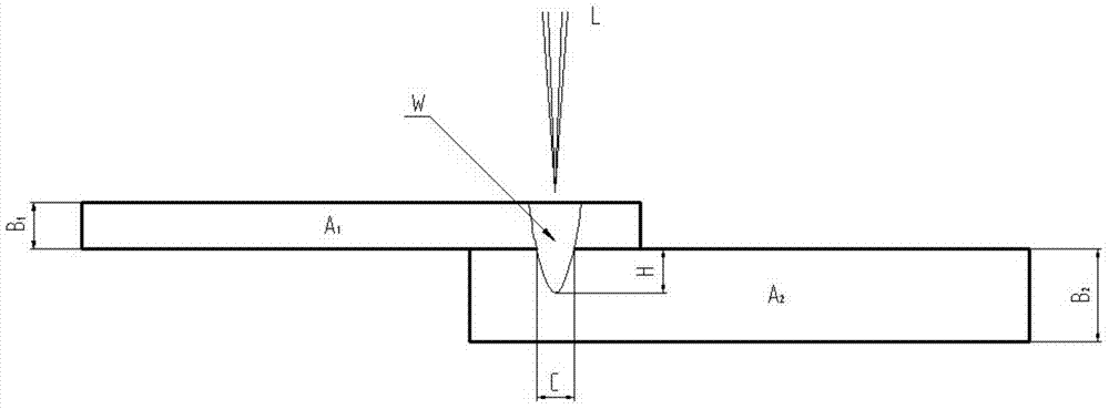
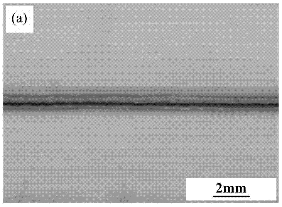
[0025] Embodiment 1. SUS301L austenitic stainless steel overlap laser welding connection is carried out by adopting the technology of the present invention, and the combination of stainless steel plate thickness is 1+2mm (the thickness of the upper plate is 1mm, and the thickness of the lower plate is 2mm). Before welding, put the pure copper backing plate in the tire fixture, and then place the stainless steel plate on the backing plate to clamp; the laser welding parameters are: laser power 1.9kW, defocus -0.5, welding speed 21mm / s ; After welding, the joint has no welding defects such as cracks, pores, lack of fusion, undercut, etc.; the melting width at the interface between the upper plate and the lower plate of the lap joint is 0.86mm, and the melting depth of the lower plate is 0.43mm; the tensile shear load of the joint is 24.3kN, and the joint The fatigue strength is 122.3MPa; there are no welding traces and oxidative discoloration on the back of the weld.

Embodiment 2

[0026] Embodiment 2: SUS301L austenitic stainless steel overlap laser welding connection is carried out by adopting the technology of the present invention, and the combination of stainless steel plate thickness is 1+2mm (the thickness of the upper plate is 1mm, and the thickness of the lower plate is 2mm). Before welding, put the pure copper backing plate in the tire fixture, and then place the stainless steel plate on the backing plate to clamp; the laser welding parameters are: laser power 2.0kW, defocus amount 1.0, welding speed 22mm / s; After welding, the joint has no welding defects such as cracks, pores, lack of fusion, and undercut; the melting width at the interface between the upper plate and the lower plate of the lap joint is 0.80mm, and the melting depth of the lower plate is 0.41mm; the tensile shear load of the joint is 24.1kN, and the joint is fatigued. The strength is 118.3MPa; there are no welding traces and oxidative discoloration on the back of the weld.

Embodiment 3

[0027] Embodiment 3. The technology of the present invention is used to carry out lap joint laser welding of SUS301L austenitic stainless steel, and the combination of stainless steel plate thickness is 1+2 mm (the thickness of the upper plate is 1 mm, and the thickness of the lower plate is 2 mm). Before welding, put the pure copper backing plate in the tire fixture, and then place the stainless steel plate on the backing plate to clamp; the laser welding parameters are: laser power 2.1kW, defocus amount 0.5, welding speed 23mm / s; After welding, the joint has no welding defects such as cracks, pores, lack of fusion, and undercut; the melting width at the interface between the upper plate and the lower plate of the lap joint is 0.72mm, and the melting depth of the lower plate is 0.35mm; the tensile shear load of the joint is 22.9kN, and the joint is fatigued. The strength is 111.7MPa; there are no welding traces and oxidative discoloration on the back of the weld.


PUM

PropertyMeasurementUnit
Plate thicknessaaaaaaaaaa

Abstract

The invention relates to the technical field of railway vehicles, machinery, materials and the like, and relates to an austenite stainless steel lap-over laser welding method. The method aims to the problems existing in stainless steel railway bus body resistance spot-welding and structures of car body side walls, is based on influence rules of laser welding characteristics and parameters on infusion depth, infusion width, microstructure, mechanical property and welding seam back face oxidation stain degree of austenite stainless steel lap-over non-penetration welding head, and adopts an orthogonal design test method to optimize laser welding parameters; through the technological approaches that the melting width C at the interface of the upper plate and the lower plate of a lap-over joint is properly increased to be greater than 0.6B1 and the melting depth H of the lower plate is limited to be smaller than 0.5 mm, the mechanical property of the stainless steel lap-over laser welding head is improved, the welding seam back face oxidation stain is prevented, and the welding quality of the laser welding head is improved. The method comprises the following technological steps: placing a pure copper base plate under a welding piece; adopting optimized laser welding parameters; realizing stainless steel lap-over laser welding connection.

Description

technical field [0001] The invention relates to an austenitic stainless steel lap joint laser welding technology in the technical fields of rail vehicles, machinery and materials, and belongs to the technical field of material connection. Background technique [0002] With the increasing energy shortage and environmental pollution, the rail vehicle industry, which is the pillar industry of the manufacturing industry, is facing more and more severe challenges. Lightweight, energy saving, environmental protection and safety have become the inevitable trend of the development of today's rail vehicle industry. Among various materials and types of rail passenger vehicles, stainless steel rail passenger vehicles have become the first choice for rail passenger vehicles due to their advantages such as light weight, low energy consumption, corrosion resistance, good safety, long service life and low overall cost. In particular, stainless steel high-speed EMU products have broader ap...

Claims


Application Information

Patent Timeline
IPC IPC(8): B23K26/244B23K26/32B23K26/70
CPCB23K26/32B23K26/12B23K26/244B23K26/60B23K2101/18B23K2103/04B23K2103/50
Inventor 孙大千李洪梅谷晓燕
Owner JILIN UNIV
Why Eureka
Try Eureka