Method and device for recovering molten blast furnace slag sensible heat

A technology of blast furnace slag and molten slag, which is applied in secondary energy recovery, iron and steel metallurgy energy saving and emission reduction fields, and can solve problems such as hot water and steam affecting production, inability to adapt to three seasons, and low utilization rate of slag heat energy

Active Publication Date: 2014-01-01
鞍钢集团工程技术有限公司
View PDF4 Cites 9 Cited by
  • Summary
  • Abstract
  • Description
  • Claims
  • Application Information

AI Technical Summary

Problems solved by technology

[0004] At present, the sensible heat utilization rate of blast furnace slag in my country is extremely low, and most enterprises adopt water slag treatment process, and the so-called utilization means that northern enterprises use blast furnace slag flushing water for heating in winter, due to the limitation of heating area, flow rate and other conditions, and The slag flushing water contains a large amount of alkaline substances, which will cause corrosion of pumps and pipelines. The utilization rate of slag heat energy is extremely low, and it cannot be adapted to the three seasons of spring, summer, and autumn. A large amount of hot water and steam affect production.

Method used


Image

  • Method and device for recovering molten blast furnace slag sensible heat
  • Method and device for recovering molten blast furnace slag sensible heat
  • Method and device for recovering molten blast furnace slag sensible heat

Examples


Embodiment Construction

[0016] The specific embodiment of the present invention will be further described below in conjunction with accompanying drawing:

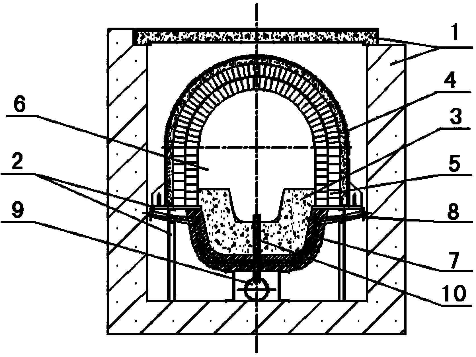
[0017] See figure 1 , is a structural schematic diagram of an embodiment of the bottom-blowing composite molten slag ditch of the present invention, including a cement outer slag ditch 1, a ditch body support 2, a ditch body 3 and a ditch cover 4, and the bottom of the cement outer slag ditch 1 is provided with a ditch body support 2, and the ditch The upper part of the body support 2 is provided with a ditch body 3 and a ditch cover 4 made of refractory materials, and the inner surface of the ditch cover 4 is provided with a heat storage masonry 5, and a slag flow channel 6 is formed between the ditch body 3 and the ditch cover 4 , the bottom of ditch body 3 is provided with copper stave 7, the copper stave 7 is provided with cooling water pipe 8, the bottom of copper stave 7 is provided with bottom blowing air pipe 9, and the bottom blowing air ...


PUM


Abstract

The invention belongs to the technical field of energy recovery, and particularly relates to a method and device for recovering molten blast furnace slag sensible heat. The process of the method sequentially includes the following steps that (1) blast furnace slag enters a segmented bottom blowing composite molten slag trough, compressed air is blown in from the bottom of the bottom blowing composite molten slag trough, and at the moment a heat accumulator is heated to be within the range from 1100 DEG C to 1250 DEG C; (2) molten slag of which the temperature is reduced to be within the range of 700 DEG C to 800 DEG C enters an old slag processing system through a connecting unit, and then follow-up processing is conducted on slag; (3) when slag stops being discharged from a blast furnace, air is still blown in from the bottom of the bottom blowing composite molten slag trough, and air is heated to be within the range from 800 DEG C to 900 DEG C when passing through the heat accumulator; (4) hot air is used for power generation after being dedusted, and then cooling water replaces heat for production. Compared with the prior art, the method and device have the advantages that through the improvement, heat can be efficiently recovered, the temperature of combustion air by a hot blast heater can be increased, the device and method can be also used for waste heat power generation, and then the purpose of energy reutilization is achieved.

Description

technical field [0001] The invention belongs to the technical field of iron and steel metallurgy energy saving and emission reduction and secondary energy recovery, and in particular relates to a method and a device for recovering sensible heat of molten blast furnace slag. Background technique [0002] The iron and steel industry is an important basic industry of my country's national economy. Since the 1990s, my country's iron and steel industry has developed rapidly. In 2012, the output of crude steel reached 720 million tons, of which the output of blast furnace pig iron (that is, long-process crude steel production) was close to 659 million tons. , with the growth of iron and steel production, the total amount of solid waste produced by the iron and steel industry is increasing. Among the solid waste, blast furnace slag accounts for a large proportion. Blast furnace slag emissions vary with ore grade and smelting method. Generally speaking, when the charge grade reaches...

Claims


Application Information

Patent Timeline
Patent Type & Authority Applications(China)
IPC IPC(8): C21B5/00C21B3/08F27D17/00
CPCY02P10/20Y02P10/25
Inventor 张维巍李霞赵波
Owner 鞍钢集团工程技术有限公司
Why Eureka
Try Eureka