Hydraulic speed retarding device adopting engine oil as medium

An engine oil and hydraulic retarding technology, which is applied in the direction of engine components, engine lubrication, machine/engine, etc., can solve the problems of increasing the volume, quality, cost and assembly difficulty of hydraulic retarding devices, and achieve compact structure, Simplified structure and light weight effect

Active Publication Date: 2015-07-22
JIANGSU UNIV OF TECH
View PDF10 Cites 0 Cited by
  • Summary
  • Abstract
  • Description
  • Claims
  • Application Information

AI Technical Summary

Problems solved by technology

However, this hydraulic retarder needs a relatively large oil storage tank and a long coolant pipeline connecting the engine cooling system and the oil-water heat exchanger, which increases the volume, quality, cost and cost of the hydraulic retarder. Assembly difficulty

Method used


Image

  • Hydraulic speed retarding device adopting engine oil as medium
  • Hydraulic speed retarding device adopting engine oil as medium
  • Hydraulic speed retarding device adopting engine oil as medium

Examples


Embodiment 1

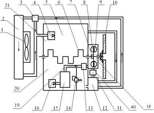
[0026] Such as figure 1 , 3 , shown in 4, an engine oil medium type hydraulic retarder, including a hydraulic retarder and a control unit that can control the work of the hydraulic retarder, the hydraulic retarder is installed on the vehicle engine crankshaft 6 and flywheel 10 between, and the hydraulic retarder has a retarder working chamber 18, which also includes an inlet pipe 19, an outlet pipe 40, an engine oil pump 16, and an inlet throttle valve 13 for controlling the oil flow in the inlet pipe 19 and controlling the outlet pipe Outlet throttle valve 11 for engine oil circulation in 40, engine oil pump 16 is arranged in engine oil chamber 20, engine oil pump 16, inlet pipe 19, slow speed working chamber 18, outlet pipe 40 and engine oil chamber 20 are connected in sequence A circulation pipeline is formed, the inlet throttle valve 13 is connected to the inlet pipeline 19, the outlet throttle valve 11 is connected to the outlet pipeline 40, and the inlet throttle valve ...

Embodiment 2

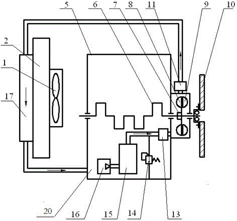
[0040] Such as figure 2 As shown, the present embodiment is similar to Embodiment 1, and the difference is that the oil cooler includes an oil radiator 17 and an engine radiator 2, the oil radiator 17 is installed on the engine radiator 2, and the oil inlet end of the oil radiator 17 It communicates with the outlet throttle valve 11 , and the oil outlet of the oil radiator 17 communicates with the engine oil chamber 20 . This embodiment cancels the oil-water heat exchanger 12 in the first embodiment, but is provided with a special oil radiator 17, which is installed in front of the engine radiator 2. When the hydraulic retarder is working, after energy absorption and heating The engine oil enters the engine oil radiator 17 from the top through the outlet throttle valve 11, and the engine oil after being cooled by the natural wind of the vehicle and the cooling fan 1 directly returns to the engine oil chamber 20, so that the continuous circulation will make the hydraulic retar...


PUM


Abstract

The invention discloses a hydraulic speed retarding device adopting engine oil as a medium. The hydraulic speed retarding device comprises a hydraulic retarder and a control unit which can be used for controlling the working of the hydraulic retarder, wherein the hydraulic retarder is installed between a vehicle engine crankshaft and flywheels, and the hydraulic retarder is provided with a speed retarding working cavity; the hydraulic speed retarding device further comprises an inlet pipeline, an outlet pipeline, an engine oil pump, an inlet throttle and an outlet throttle, wherein the engine oil pump is arranged in an engine oil cavity, the engine oil pump, the inlet pipeline, the speed retarding working cavity, the outlet pipeline and the engine oil cavity are communicated in sequence to form a circulating pipeline, the inlet throttle is connected to the inlet pipeline, the outlet throttle is connected to the outlet pipeline, and the inlet throttle and the outlet throttle are respectively in control connection with the control unit. According to the hydraulic speed retarding device, the engine oil is adopted as a working medium, an oil storage tank of the traditional hydraulic retarder is replaced by an engine oil bottom case, so that speed retarding braking function can be effectively provided, and the hydraulic speed retarding device has the advantages of small size, light weight, low cost and compact structure and is convenient to assemble.

Description

technical field [0001] The invention relates to an engine oil medium type hydraulic retarder, which belongs to the technical field of vehicle auxiliary braking. Background technique [0002] When the vehicle is under continuous braking for a long time, high-intensity braking or frequent braking, the temperature of the brake disc or brake drum will increase significantly, resulting in a decrease in the friction factor, aggravated wear, and partial or even complete loss of braking performance. Dangerous thermal recession phenomenon. Although the application of anti-lock brake system (ABS) and electronic brake force distribution system (EBD) has improved the stability and reliability of vehicle braking, they have little effect on the thermal fading phenomenon of brakes. At present, many countries including my country have clearly stipulated that passenger cars and trucks above a certain specification must be equipped with auxiliary braking devices to effectively divert the...

Claims


Application Information

Patent Timeline
Patent Type & Authority Patents(China)
IPC IPC(8): F16D65/28F16D65/78F16D57/00F16D67/02F02N19/10F01M5/02
Inventor 王奎洋贝绍轶唐金花汪永志
Owner JIANGSU UNIV OF TECH
Why Eureka
Try Eureka