An optical fiber output photoelectric encoder

A photoelectric encoder and encoder technology, applied in the field of photoelectric encoders, can solve the problems of electrical working parts affected by the environment, use restrictions, and high waterproof requirements, and achieve high bandwidth, enhanced insulation performance, and strong corrosion resistance.

Active Publication Date: 2016-03-09
YANGTZE OPTICAL FIBRE & CABLE CO LTD
View PDF3 Cites 0 Cited by
  • Summary
  • Abstract
  • Description
  • Claims
  • Application Information

AI Technical Summary

Problems solved by technology

[0004] The technical problem to be solved by the present invention is to provide a photoelectric encoder with optical fiber output and its measurement method for the defect that the existing photoelectric encoder has the above-mentioned electrical working parts affected by the environment, so as to eliminate the defect and solve the problem of the encoder in high voltage, Restricted use under special harsh conditions such as electrical, corrosion, flammable and explosive, and high waterproof requirements

Method used


Image

  • An optical fiber output photoelectric encoder
  • An optical fiber output photoelectric encoder
  • An optical fiber output photoelectric encoder

Examples


Embodiment 1

[0030] Embodiment 1: Optical encoder for optical fiber output of rotational parameters in oil gas or corrosive environment.

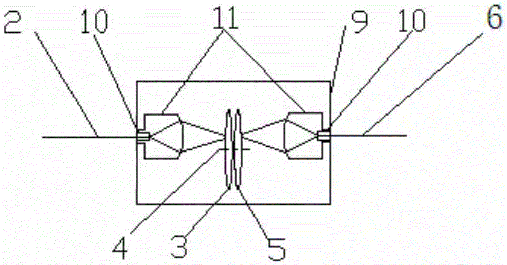
[0031] refer to image 3 , Example 1 with figure 2 The difference in structure is that two collimators 11 are added, which are respectively located between the input optical fiber 2 and the code disc 3 , and between the slit disc 5 and the output optical fiber 6 .

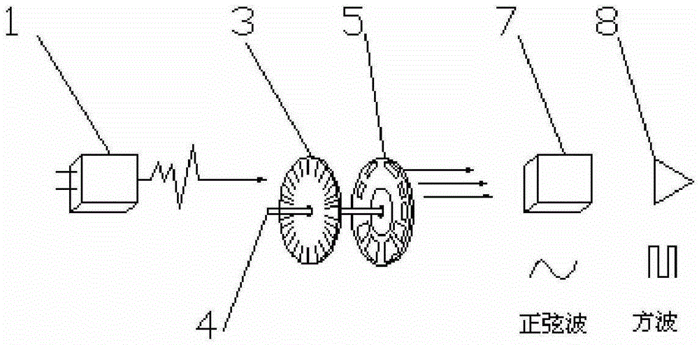
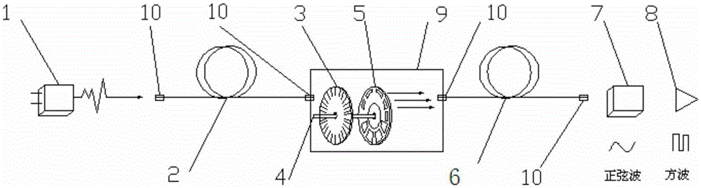
[0032] The light source 1 is an infrared light-emitting diode, the receiver 7 is a silicon phototransistor, the input optical fiber 2 and the output optical fiber 6 are plastic optical fibers, and the length of the transmission part of the input optical fiber 2 and output optical fiber 6 is 30m. The code disc 3 is a rotary type, and is placed in the encoder housing 9 together with the slit disc 5 and the support shaft 4. The code disc 3 adopts a matrix pattern, and the base material of the code disc 3 is K9 optical glass. The diameter of the code disc depends on the 3 digits, the diameter...

Embodiment 2

[0033] Embodiment 2: A photoelectric encoder for measuring rotation and angle parameters in a high-voltage environment with optical fiber output.

[0034] refer to Figure 4 , Example 2 with figure 2 The difference in structure is that a focusing lens 13 or a focusing lens group is added, which is located between the input optical fiber 2 and the code wheel 3 .

[0035]The light source 1 is an infrared light-emitting diode, the receiver 7 is a silicon phototransistor, the input optical fiber 2 and the output optical fiber 6 are multi-component glass optical fibers, and the length of the transmission part of the input optical fiber 2 and output optical fiber 6 is 1000m. The code disc 3 is a translational type. It is placed in the encoder housing 9 together with the slit disc 5 and the support shaft 4. The code disc 3 is engraved with radial light-transmitting slits with equal pitches. Between two adjacent light-transmitting slits The interval represents an incremental period...

Embodiment 3

[0036] Embodiment 3: A photoelectric encoder with optical fiber output for measuring rotation and angle parameters in a deep-sea environment.

[0037] refer to Figure 5 , Example 3 with figure 2 The structural difference is that a collimating device 14 is provided between the input optical fiber 2 and the code disk 3 , and a focusing device 15 is provided between the slit disk 5 and the output optical fiber 6 .

[0038] The light source 1 is a near-infrared laser, the receiver 7 is a silicon phototransistor, the input fiber 2 and the output fiber 6 are pure silicon core bending-resistant quartz fibers, and the length of the transmission part of the input fiber 2 and output fiber 6 is 8000m. The code disc 3 is a rotary type, and is placed in the encoder housing 9 together with the slit disc 5 and the support shaft 4. The slit disc 5 is engraved with a single slit (light-transmitting slit) corresponding to the 9-bit code disc 3 .

[0039] The input optical fiber 2 and the ou...


PUM


Abstract

An optical fiber output photoelectric encoder comprises a light source, a code disk, a supporting shaft, a slit disk, a receiver and a decoder. The code disk and the slit disk are arranged on the supporting shaft. The optical fiber output photoelectric encoder further comprises at least one optical fiber and at least one output optical fiber, wherein the input optical fiber is matched and connected with the light source, and the output optical fiber is matched and connected with the receiver. The light signals emitted by the light source are transmitted to the code disk through one input optical fiber, the code disk can modulate the light signals and transmit the modulated light signals to the receiver through one output optical fiber or a plurality of output optical fibers, and the decoder can decode the signals received by the receiver to obtain the corresponding position of the code disk. The photoelectric encoder further comprises an encoder casing, the light source, the input fiber, the output optical fibers, the receiver and the decoder are arranged outside the encoder casing, and the code disk, the supporting shaft and the slit disk are arranged in the encoder casing. The optical fiber output photoelectric encoder has the advantages of solving the problem that the photoelectric encoder is limited to be used in special and severe conditions of with high-pressure, electric, corrosive, flammable, combustible and waterproof requirements.

Description

technical field [0001] The invention relates to the technical field of optical fiber sensing and measurement, in particular to a photoelectric encoder with optical fiber output. Background technique [0002] The photoelectric encoder is an angle (angular velocity) detection device that converts the angle of the input shaft into corresponding electrical pulses or digital quantities using the principle of photoelectric conversion. It has the advantages of small size, high precision, reliable operation, and digital interface. It is widely used. It is used in devices and equipment that need to detect angles, such as CNC machine tools, rotary tables, servo drives, robots, radars, and military target measurement. The photoelectric encoder is composed of a grating disk and a photoelectric detection device. The grating disk is opened with several rectangular holes in equal parts on a circular plate with a certain diameter. Since the photoelectric code disk is coaxial with the motor,...

Claims


Application Information

Patent Timeline
Patent Type & Authority Patents(China)
IPC IPC(8): G01D5/347
Inventor 何珍宝陈波曹蓓蓓
Owner YANGTZE OPTICAL FIBRE & CABLE CO LTD
Why Eureka
Try Eureka