Method for designing magnetism-keeping parallel stepping swinging stretchy joint

A design method and magnetic retention technology, applied in the direction of electromagnet, motor generator control, electromagnet with armature, etc., can solve the problem of only turning, unable to meet the requirements of high-end technology, single robot joint and so on

Active Publication Date: 2014-01-01
滁州岳众汽车零部件有限公司
View PDF3 Cites 9 Cited by
  • Summary
  • Abstract
  • Description
  • Claims
  • Application Information

AI Technical Summary

Problems solved by technology

The disadvantages are: (1) The viscosity of the oil changes with the temperature, which affects the working performance. Higher; (3) Requires a corresponding oil supply system, especially an electro-hydraulic servo system that requires a strict oil filter device, otherwise it will cause failure
The disadvantages are: (1) The common pressure of compressed air is 0.4-0.6MPa. If a larger force is to be obtained, the structure must be relatively enlarged; (2) The air is highly compressible, the work stability is poor, and the speed control is difficult. Accurate position control is very difficult; (3) The water removal problem of compressed air is a very important problem. Improper handling will cause steel parts to rust and cause the robot to fail
But the above three kinds of drivers still have common deficiencies, 1. Slow response speed, 2. High power consumption or fuel consumption, 3. Large size, 4. Too heavy weight, 5. Poor flexibility, 6. Complex structure, 7. The accuracy is average, 8. The control is difficult, and the joints of the current robot are relatively simple, some can only turn, some can only push, not as flexible as human joints
It simply cannot meet the requirements of high-end technology, let alone meet the design requirements of intelligent robots, so we must invent new technologies to meet the joint requirements of high-end intelligent robots

Method used


Image

  • Method for designing magnetism-keeping parallel stepping swinging stretchy joint
  • Method for designing magnetism-keeping parallel stepping swinging stretchy joint
  • Method for designing magnetism-keeping parallel stepping swinging stretchy joint

Examples


Embodiment Construction

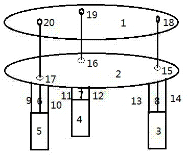
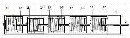
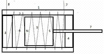
[0006] The magnetically held parallel step swing telescopic joint works under the action of the processor and the encoder. When the processor gives a positive pulse voltage to a certain unit in the magnetically held parallel step driver, the magnetically held drive passes through the peripheral circuit. , a positive pulse current will be given to the magnetic holding driver of this unit, and the magnetic holding driver of this unit will move forward, and the encoder will record the state of the magnetic holding driver of this unit. A reverse voltage of a magnetic holding driver of a certain unit, through the peripheral circuit, will give a reverse pulse current to the magnetic holding driver of this unit, the magnetic holding driver of this unit will retract backward, and the encoder will record this unit The state of the magnetic holding drive, and a sensor is installed at the front or rear end of each unit magnetic holding drive. The state of each unit magnetic holding drive...


PUM


Abstract

The invention relates to the technical field of magnetism-keeping parallel stepping swinging stretchy joints, and belongs to the fields of machine manufacturing, intelligent control, the robot technology, automatic control and the electromagnetic technology. According to the main technical content, a magnetism-keeping parallel stepping swinging face and a magnetism-keeping parallel stepping driver are combined together to form a mechanical joint which can swing and be stretched. The magnetism-keeping parallel stepping swinging face and a driving unit of the magnetism-keeping parallel stepping driver are both composed of unit magnetism-keeping drivers, and therefore parallel execution can be achieved. Only one pulse time is required, the swinging face can be swung to the required direction and angle, and meanwhile the magnetism-keeping parallel stepping driver can be stretched to be the required length.

Description

technical field [0001] The technical field of magnetically held parallel stepping swing telescopic joints belongs to the field of machinery manufacturing, intelligent control, robotics, automation control, and electromagnetic technology. Combined together, a mechanical joint that can swing and stretch is formed. The drive unit of the magnetically held parallel stepping swing surface and the magnetically held parallel stepping driver is composed of a magnetically held driver, so it can be executed in parallel and only needs one pulse time. , you can swing the swing surface to the required direction and angle, and at the same time, the magnetic holding parallel stepper driver can be stretched to the required length. Background technique [0002] With the unprecedented development of robots, robots are gradually appearing in all walks of life of human beings. The impact of robots on humans is becoming more and more important. With the continuous reduction of robot costs, robots...

Claims


Application Information

Patent Timeline
Patent Type & Authority Applications(China)
IPC IPC(8): H02P8/40H01F7/08
Inventor 胡明建
Owner 滁州岳众汽车零部件有限公司
Why Eureka
Try Eureka