Casting apparatus and casting method

A crucible and molten material technology, applied in stirring devices, casting equipment, chemical instruments and methods, etc., can solve problems such as the decline in the yield of ingots, and achieve the effect of reducing foreign matter and impurity prevention.

Active Publication Date: 2014-01-08
MITSUBISHI MATERIALS CORP
View PDF5 Cites 3 Cited by
  • Summary
  • Abstract
  • Description
  • Claims
  • Application Information

AI Technical Summary

Problems solved by technology

When this slagging occurs, it is necessary to separate the slagging part from the ingot, and the yield of the ingot decreases.

Method used


Image

  • Casting apparatus and casting method
  • Casting apparatus and casting method
  • Casting apparatus and casting method

Examples


no. 1 approach 〉

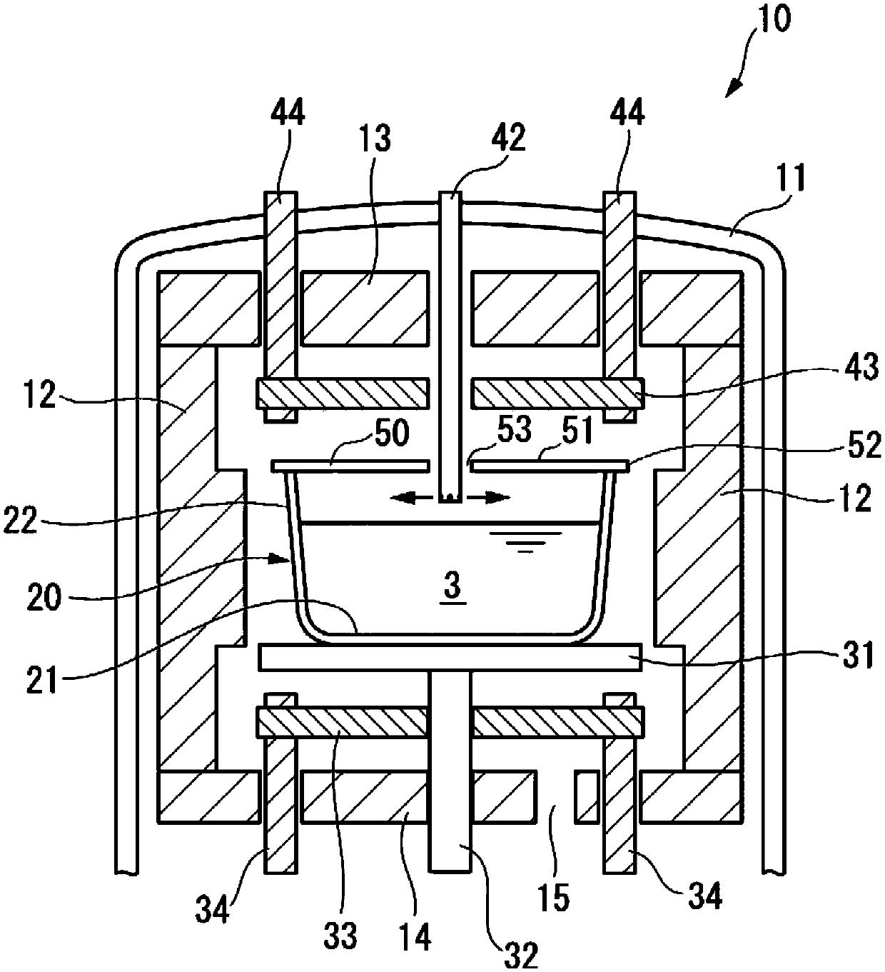
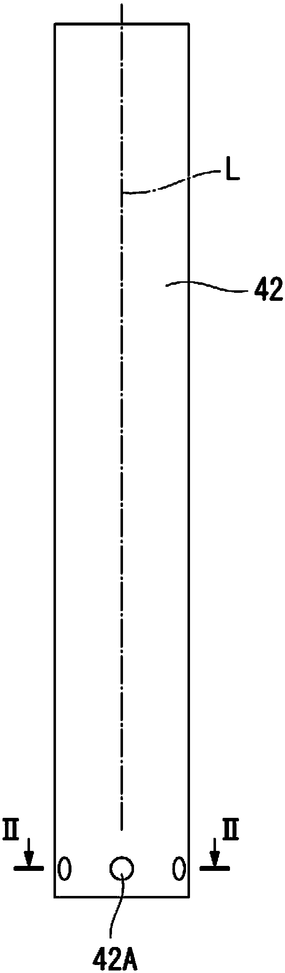
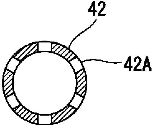
[0070] Figure 1 ~ Figure 5C The first embodiment of the casting device according to the present invention is shown. figure 1 It is a schematic cross-sectional explanatory view of the first embodiment. The casting apparatus 10 of the present embodiment includes a chamber 11 keeping the inside in an airtight state, a crucible 20 storing the silicon melt 3 , a chill plate 31 on which the crucible 20 is placed, and a The lower heater 33 , the upper heater 43 located above the crucible 20 , the cover 50 placed on the upper end of the crucible 20 , and a gas that introduces an inert gas (for example, argon) into the space between the crucible 20 and the cover 50 supply pipe 42 .

[0071] In addition, an insulating wall 12 is arranged on the outer peripheral side of the crucible 20 , an insulating top plate 13 is arranged above the upper heater 43 , and an insulating bottom plate 14 is arranged below the lower heater 33 . That is, in the casting apparatus 10 of the present embodi...

no. 2 approach 〉

[0098] Figure 6A ~ Figure 8B A second embodiment of the casting apparatus according to the present invention is shown. Figure 6A and Figure 6B It is a figure which shows the main part of 2nd Embodiment of the casting apparatus of this invention. Figure 6A is the side view of the gas channel, Figure 6B is a top view of the gas channel.

[0099] The difference between the second embodiment and the above-mentioned first embodiment is only the gas channel, and the other structures are the same as those of the first embodiment, and the description of the same parts will be omitted here.

[0100] The gas passage 60 of the second embodiment connects the base end side to the gas supply part, and includes a gas supply main pipe 61 arranged with the front end facing the upper space of the crucible, and a plurality of gas supply branch pipes branched from the front end of the gas supply pipe 61. 62.

[0101] The gas supply pipe 61 is arranged to extend in the vertical direction...

no. 3 approach >

[0111] Figure 9 , Figure 10 A third embodiment of the casting apparatus according to the present invention is shown. Figure 9 It is a perspective view which shows the main part of 3rd Embodiment of the casting apparatus of this invention.

[0112] This embodiment is also the same as the second embodiment, and the configuration other than the characteristic portion of the gas passage is the same as that of the above-mentioned first embodiment, so description thereof will be omitted.

[0113] The gas passage 70 of the third embodiment connects the base end side to the gas supply part, and includes a gas supply main pipe 71 arranged with the front end facing the upper space of the crucible, and a plurality of gas supply branch pipes 72 branched from the front end of the gas supply main pipe 71 .

[0114] The gas supply main pipe 71 is arranged to extend in the vertical direction, and is arranged to penetrate figure 1 The top plate of the chamber 11 shown passes through the...


PUM

PropertyMeasurementUnit
Particle sizeaaaaaaaaaa
Thicknessaaaaaaaaaa

Abstract

The casting apparatus comprises a crucible (20) that stores a melt and has an opening on its upper side, a heater for heating the crucible, and a device for supplying an inert gas to an upper portion of an interior of the crucible, where the inert gas supplying device extends to the upper portion of the interior of the crucible and includes a gas flow passage and a gas discharging hole located at a distal end portion of the inert gas supply device. The gas flow passage includes a main gas supply tube placed in a distal end of upper portion of the crucible. The casting apparatus comprises a crucible (20) that stores a melt and has an opening on its upper side, a heater for heating the crucible, and a device for supplying an inert gas to an upper portion of an interior of the crucible, where the inert gas supplying device extends to the upper portion of the interior of the crucible and includes a gas flow passage and a gas discharging hole located at a distal end portion of the inert gas supply device. The gas discharge hole is provided such that a flow of the supplied inert gas from the gas discharging hole is parallel to a surface of the melt in the crucible or is inclined at a predetermined angle to the surface of the melt in the crucible. The gas flow passage includes a main gas supply tube placed in a distal end of upper portion of the crucible, and the gas discharge hole is formed in a side surface of a distal end portion of the gas supply tube. The gas flow passage further includes gas supply pipes branched from a distal end of the main gas supply pipe. The branched gas supply pipes are arranged parallel to the surface of the melt in the crucible. The gas discharge hole is provided in a distal end of the branched gas supply pipes. An independent claim is included for a casting process.

Description

technical field [0001] The present invention relates to a casting device and a casting method for producing semiconductors such as polycrystalline silicon or metal ingots. Background technique [0002] The silicon ingot becomes a silicon wafer by being cut into a predetermined thickness and cut into a predetermined shape. [0003] A silicon wafer is used, for example, as a material for a substrate for a solar cell. Here, in a solar cell, performance such as conversion efficiency is greatly influenced by the characteristics of a silicon ingot that is a material of a substrate for a solar cell. [0004] In particular, if the amount of impurities contained in a silicon ingot is large, the conversion efficiency of the solar cell will be greatly reduced. Therefore, it is necessary to reduce the amount of impurities in order to improve the conversion efficiency. [0005] Here, silicon is a metal that expands when solidified, and is casted by solidifying, for example, unidirectio...

Claims


Application Information

Patent Timeline
IPC IPC(8): C30B29/06C30B11/00C30B28/06B22D27/04B22D7/06
CPCC30B28/06B22D27/00B22D23/06C30B29/06F27B14/04C30B11/002B22D41/005F27B14/06B22D21/02B22D27/04F27D2003/166F27D2003/167F27D2027/002
Inventor 二田伸康中田嘉信
Owner MITSUBISHI MATERIALS CORP
Why Eureka
Try Eureka