Multi-motor synchronous coordination control method

A technology of synchronous coordination and control method, which is applied in AC motor transmission occasions, multi-motor transmission occasions, and multi-motor synchronous coordination control fields, and can solve problems such as motor out-of-synchronization and shortage

Inactive Publication Date: 2014-01-08
中国船舶重工集团公司第七一二研究所
View PDF6 Cites 32 Cited by
  • Summary
  • Abstract
  • Description
  • Claims
  • Application Information

AI Technical Summary

Problems solved by technology

The synchronous coordinated control performance of the master and slave motors in the prior art is insufficient. Among them, the multi-motor parallel coordinated control uses the output of the master motor as the input of the slave motors, so that the slave motors follow the master motor. When the time changes, the main motor does not have any feedback information from the slave motor, which causes the motor to lose synchronization

Method used


Image

  • Multi-motor synchronous coordination control method
  • Multi-motor synchronous coordination control method

Examples


Embodiment 1

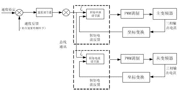
[0023] Example 1: This is the basic embodiment of the present invention. As shown in the figure, a multi-motor synchronous coordinated control method is characterized by including the following steps:

[0024] A. Obtain the given value of torque current: According to the given value and feedback value of the outer loop of the main inverter speed, the given value of torque current is obtained after PI adjustment ;

[0025] B. Obtain excitation current and torque current feedback value: detect the output three-phase current of each motor, and obtain the feedback value of excitation current and torque current through coordinate transformation;

[0026] C. Transmission of torque current given value: the given value of torque current between master and slave control Transmission between motors via CAN bus communication;

[0027] D. Obtain the current control value of each motor: compare the given torque current value with the feedback torque current value of the master and slave motors,...

Embodiment 2

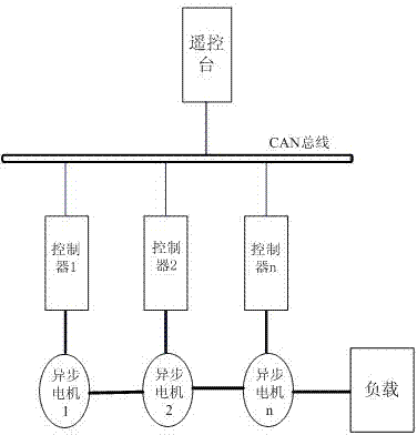
[0030] Example 2: This is a further embodiment of the present invention on the basis of Embodiment 1. The difference from Embodiment 1 is: in the multi-motor synchronous and coordinated control method, the master-slave control is controlled by one master inverter and multiple slave inverters; The two frequency converters are connected by optical fiber. In order to make the inverter unit have good drive compatibility, it can be driven in parallel or individually by multiple units, which can expand the drive capacity of the system and ensure the redundancy of the equipment; The inverter adopts dual-loop control. After the main inverter is controlled by the speed loop, the output torque current set value is used as the set value of the torque current inner loop of the slave inverter; it is used to take a process variable controlled by the main inverter as The given value of the slave inverter makes the synchronization performance of the master-slave inverter control better, and a...


PUM


Abstract

The invention relates to a multi-motor synchronous coordination control method, which includes the following steps: acquiring the given value of torque current, acquiring exciting current and torque current feedback values, transmitting the given value of torque current, acquiring the current control quantity of each motor, controlling each motor with a pulse control signal and the like. Inverters are a master inverter and a slave inverter, the master inverter is a master motor inverter, and the slave inverter is a slave motor inverter; and master control and slave control are carried out between the inverters. By coordinatively controlling inverter control units, the method can ensure that a plurality of motors can operate in a synchronous state; a shared rotational speed loop is adopted in an algorithm to generate torque current tracked by each inverter, the value is transmitted via a CAN (Controller Area Network) bus, consequently, delay can be shortened, and thereby the coordinating performance and reliability of a system are enhanced; and the method not only ensures that the motors have the same rotational speed, but also ensures that load can be reasonably distributed between the motors.

Description

technical field [0001] The invention relates to a multi-motor synchronous coordinated control method, which belongs to the technical field of motor control, and is particularly suitable for AC motor transmission occasions, including multi-motor transmission occasions such as ship propulsion and rail transit. Background technique [0002] With the wide application of multi-motor drives, synchronous and coordinated control of multi-motors has become a concern in industrial production control. Due to the needs of production, the motors that control the drive shaft are generally independent of each other, and the efficiency of the production process is closely related to the product quality and the control performance of the drive motor, which puts forward higher requirements for the parallel coordinated control of the inverter. Several different synchronous control strategies have been developed for multi-motor parallel transmission systems using frequency conversion technology...

Claims


Application Information

Patent Timeline
Patent Type & Authority Applications(China)
IPC IPC(8): H02P5/46H02P21/00
Inventor 康乐徐鸿李帆王锐
Owner 中国船舶重工集团公司第七一二研究所
Why Eureka
Try Eureka