
Sintering method of NdFeB magnet

A sintering method and NdFeB technology, applied in the manufacture of magnetic objects, magnetic materials, inductors/transformers/magnets, etc., can solve the problems of dimensional deformation, rising machining costs, waste of materials and sintering, and reduce the deformation of sintering, The effect of reducing machining allowance and convenient machining

Active Publication Date: 2015-12-02
SINO MAGNETICS TECH
View PDF4 Cites 0 Cited by
  • Summary
  • Abstract
  • Description
  • Claims
  • Application Information

AI Technical Summary

Problems solved by technology

[0002] At present, the known sintering technology for NdFeB magnets is the vacuum sintering method. This method is to discharge the NdFeB green bodies on the rack and put them into the furnace for direct firing. During the process of entering the furnace, the NdFeB green bodies will Brief exposure to air can easily cause oxidation of the green body
During the firing process, due to uneven heating and oxidation on the surface of the green body, it is easy to cause dimensional deformation after sintering. The deformation of the blank after sintering will increase the difficulty and time of subsequent machining, and the blank with serious deformation can only be scrapped or partially utilized.
In order to reduce the influence of this deformation and improve the qualified rate of the product, it is necessary to increase the machining allowance of the blank in the subsequent machining process, so that the size of the NdFeB green body needs to be designed to be large enough to allow more processing The margin will cause material waste and increase the cost of sintering and machining

Method used


Image

  • Sintering method of NdFeB magnet

Examples


Embodiment 1

[0028] In this embodiment, the specific content of each of the aforementioned steps is:

[0029] Preparation steps: Place the NdFeB green body in a graphite tray with at least one small grid, place at least one NdFeB green body in each small grid, and use high temperature resistant powder with a particle size range of 10-60μm The NdFeB green body is fully buried to isolate the air. The space in the small cell should be completely filled with high-temperature-resistant powder, so that not only can the air be isolated, but also the NdFeB green body can be well positioned in the small cell, and the position will not be easily moved. If the size of the NdFeB green body is very small, two or more NdFeB green bodies can be placed in a small cell, but it is necessary to ensure that any two NdFeB green bodies in the same small cell are separated from each other. The intervals are well spaced with high temperature resistant powder. In order to avoid bonding impurities on the surface ...

Embodiment 2

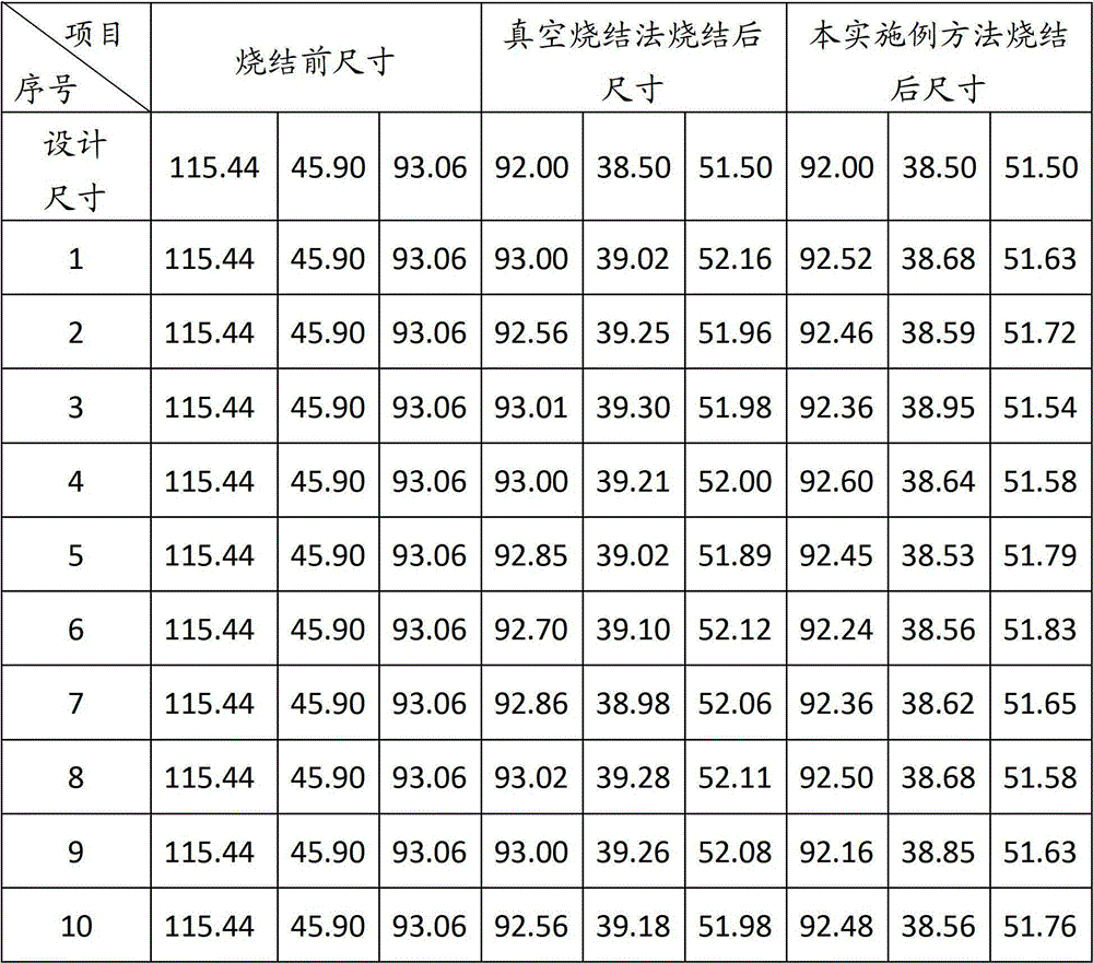
[0037] This embodiment is based on the previous embodiment, and uses a flat graphite material tray without small grids to contain the NdFeB green body and high-temperature-resistant powder, and the rest of the technical content is consistent with the previous embodiment. Since the thermal conductivity of high-temperature-resistant powder (graphite powder, alumina powder, magnesium oxide powder, or high-temperature-resistant ceramic powder) is worse than that of the graphite tray, the neodymium iron in this embodiment The heating condition of the boron green body during sintering is worse than that of the previous embodiment, but as long as the furnace temperature and sintering time are properly adjusted, the sintered size with the same statistical effect as in Table 1 can still be obtained.

Embodiment 3

[0039] In this embodiment, on the basis of the first and second embodiments, the selection scheme of the high temperature resistant powder is changed. In this embodiment, at least two of the powder materials such as graphite powder, alumina powder, magnesium oxide powder and high temperature resistant ceramic powder can be mixed with each other before being put into use. Since the above several powders do not react with each other at high temperature, the requirements of the technical solution of the present invention can be met. However, since different powders have certain differences in thermal conductivity, after mixing two or more powders, the surface heating uniformity of the NdFeB green body during the sintering process will be slightly reduced, but will not Obvious shape deformation of the NdFeB magnet can be obtained, and the sintered size similar to the statistical effect shown in Table 1 can be obtained, which can meet the requirements of the invention objective of ...


PUM

PropertyMeasurementUnit
particle diameteraaaaaaaaaa

Abstract

The invention discloses a method for sintering neodymium iron boron magnets. The method for sintering the neodymium iron boron magnets is characterized by comprising the following steps of (1) preparation, wherein neodymium iron boron green bodies are buried in high-temperature resisting powder to enable the neodymium iron boron green bodies to be isolated from air, and the sintering temperature of the high-temperature resisting powder is higher than that of the neodymium iron boron magnets; (2) furnace feeding, wherein the neodymium iron boron green bodies and the high-temperature resisting powder are fed into a sintering space in the furnace together; (3) sintering, wherein the neodymium iron boron green bodies are sintered to form the neodymium iron boron magnets. The method can reduce the oxidation of the neodymium iron boron green bodies before the neodymium iron boron green bodies are fed into the furnace, therefore, sintering deformation is reduced, reserved allowance for the machining of the neodymium iron boron green bodies is reduced, and subsequent machining is made to be convenient.

Description

technical field [0001] The invention relates to a sintering method of an NdFeB magnet. Background technique [0002] At present, the known sintering technology for NdFeB magnets is the vacuum sintering method. This method is to discharge the NdFeB green bodies on the rack and put them into the furnace for direct firing. During the process of entering the furnace, the NdFeB green bodies will Brief exposure to air can easily cause oxidation of the green body. During the firing process, due to uneven heating and oxidation on the surface of the green body, it is easy to cause dimensional deformation after sintering. The deformation of the blank after sintering will increase the difficulty and time of subsequent machining, and the blank with severe deformation can only be scrapped or partially utilized. . In order to reduce the influence of this deformation and improve the qualified rate of the product, it is necessary to increase the machining allowance of the blank in the sub...

Claims


Application Information

Patent Timeline
Patent Type & Authority Patents(China)
IPC IPC(8): B22F3/16C22C33/02H01F1/057H01F41/02
Inventor 李峰孙绪新杨时康
Owner SINO MAGNETICS TECH
Learn More