Ultraviolet fluorescence light filter used for skin damage detection and manufacturing method thereof

A technology for skin damage and optical filters, applied in optical filters, applications, diagnostic records/measurements, etc., can solve problems such as high prices, and achieve the effects of facilitating mass production and reducing the impact of manufacturing process deviations

Inactive Publication Date: 2014-01-15
HUAQIAO UNIVERSITY
View PDF3 Cites 8 Cited by
  • Summary
  • Abstract
  • Description
  • Claims
  • Application Information

AI Technical Summary

Problems solved by technology

For fingerprint identification, the filter is widely used. It is a narrow-band filter with a central wave of 254nm. For the field survey filter, its passband is 450nm~520nm, and for medical cosmetology, its passband is 200nm~550nm , and there are few domestic theoretical studies on filters for skin damage detection. In foreign countries, such filters are used, but they are expensive

Method used


Image

  • Ultraviolet fluorescence light filter used for skin damage detection and manufacturing method thereof
  • Ultraviolet fluorescence light filter used for skin damage detection and manufacturing method thereof
  • Ultraviolet fluorescence light filter used for skin damage detection and manufacturing method thereof

Examples


preparation example Construction

[0038] The present invention also relates to a preparation method of the above-mentioned ultraviolet fluorescence filter for skin damage detection, said method comprising the following steps:

[0039] Step 10, combining the optical properties of the skin to obtain the ultraviolet spectrum corresponding to the peak fluorescence of the skin, and using it as an index of the ultraviolet fluorescence filter, and its band-pass band and cut-off band;

[0040] Step 20, selecting substrate material, high refractive index film layer and low refractive index film layer material according to the index of the ultraviolet fluorescent filter;

[0041] Step 30, design film system structure and ultraviolet fluorescence filter structure according to the index of ultraviolet fluorescence filter, and carry out corresponding simulation and optimization, obtain the film system that meets the index of ultraviolet fluorescence filter; Step 40, to gained Tolerance analysis of the film system;

[0042...

Embodiment

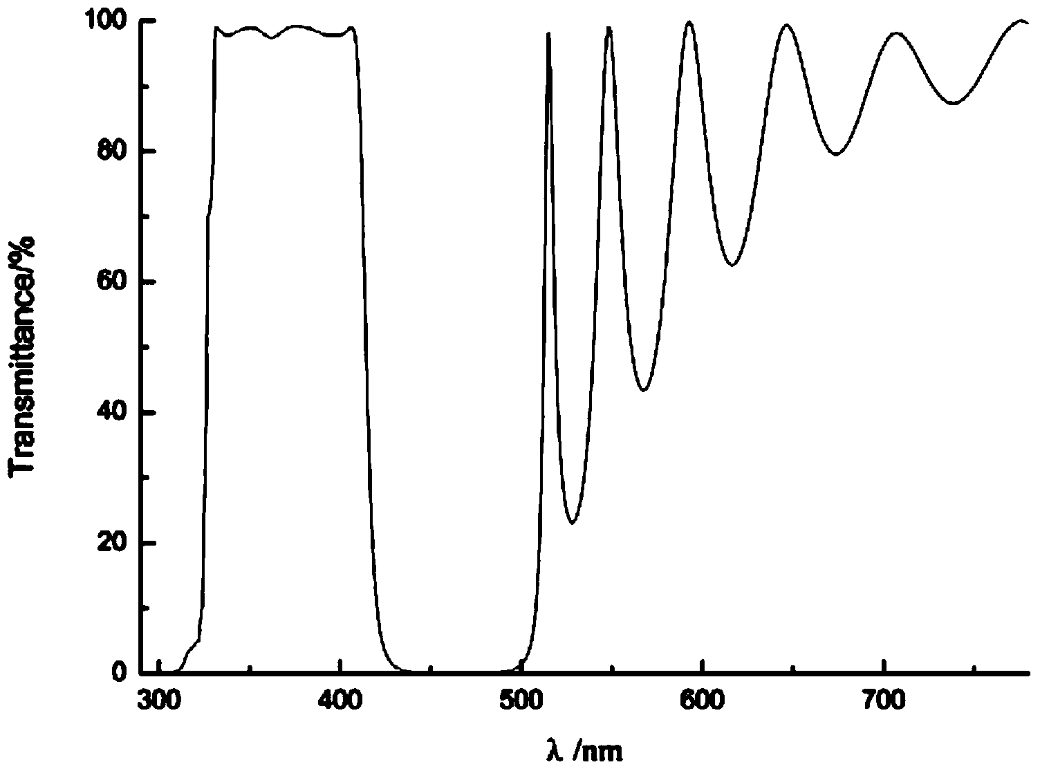
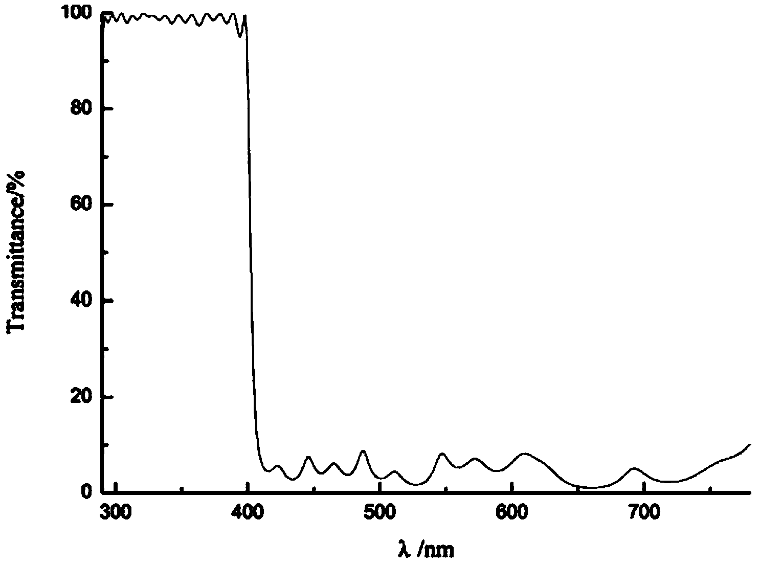
[0048] 1. Normal skin will emit fluorescence under the irradiation of ultraviolet light source, and reach the fluorescence peak when the ultraviolet light is 360nm; skin scars that are not visible to the naked eye will absorb ultraviolet light source to form a dark area, thus obtaining the UV filter The index is high transmittance in the 330nm-400nm band, the transmittance is greater than 80%, the cut-off in the 290nm-310nm and 410nm-780nm bands, the reflectance is greater than 90%, and the steepness is not more than 3%.

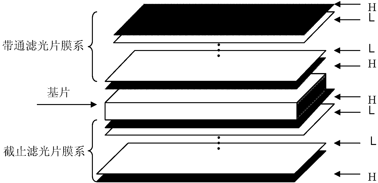
[0049] 2. According to the index of the ultraviolet filter, the substrate is selected as K9 glass, and the material of the high refractive index film layer is HfO 2 , the material of the low refractive index film layer is SiO2 .

[0050] 3. According to the index of the ultraviolet filter, as well as the selected substrate, high refractive index film layer, and low refractive index film layer material, the two sides of the substrate are designed to be plated...


PUM


Abstract

The invention provides an ultraviolet fluorescence light filter used for skin damage detection and a manufacturing method thereof. The ultraviolet fluorescence light filter comprises a substrate, a bandpass light filter film system and a stopping light filter film system, wherein the bandpass light filter film system is composed of a plurality of high-refractive-index film layers and a plurality of low-refractive-index film layers and contains a plurality of resonant cavities. The bandpass light filter film system and the stopping light filter film system are arranged on the two faces of the substrate in a plated mode respectively. The ultraviolet fluorescence light filter is high in light transmittance in the waveband of 330nm-400nm and blocks light in the wavebands of 290-310nm and 410nm-780nm. The ultraviolet fluorescence light filter can be used for capturing specific spectrums of an ultraviolet light source in ultraviolet fluorescence imaging and facilitate skin damage detection work.

Description

【Technical field】 [0001] The invention relates to an ultraviolet fluorescence filter for skin damage detection and a preparation method thereof. 【Background technique】 [0002] In recent years, imaging technology has developed rapidly. From traditional visible light imaging to infrared imaging and ultraviolet imaging, ultraviolet imaging includes two parts: ultraviolet fluorescence imaging and ultraviolet reflection imaging. Different spectral imaging is used in different fields. In the field of criminal investigation, photography of skin scars from the epidermis to the dermis can capture important evidence, such as the shape of the murder weapon, information about the murderer, etc.; in the field of dermatology, imaging of skin scars from the epidermis to the dermis can monitor the skin Health condition, medical treatment for the skin. The most critical part of the detection system is the ultraviolet bandpass filter, and the performance of the filter seriously affects the...

Claims


Application Information

Patent Timeline
Patent Type & Authority Applications(China)
IPC IPC(8): G02B5/20A61B5/00
Inventor 马钰慧邱伟彬
Owner HUAQIAO UNIVERSITY
Why Eureka
Try Eureka