Reaction device and method for hydrogen production through photocatalytic water splitting

A technology of photo-splitting water for hydrogen production and reaction device, applied in hydrogen production and other directions, can solve the problems of poor gas circulation, high linear correlation requirements, low degree of automation, etc., and meet the requirements of convenient operation and maintenance, and air tightness. Low, high degree of automation effect

Active Publication Date: 2015-04-01
湖北洛克泰克仪器股份有限公司
View PDF10 Cites 0 Cited by
  • Summary
  • Abstract
  • Description
  • Claims
  • Application Information

AI Technical Summary

Problems solved by technology

There are many valves used in the whole device. During the operation process, it is necessary to control the flow direction of the gas by continuously turning the specially designed valves. The operation steps are cumbersome and the degree of automation is low.
When the amount of gas generated is large, the gas in the pipeline will not circulate smoothly, resulting in large errors in measurement data
At the same time, conventional devices must obtain a standard curve before carrying out the experiment of monitoring catalyst activity, and have high requirements for linear correlation.
Due to the complexity of the whole set of devices, any link may cause the linear correlation of the standard curve to fail to meet the requirements, and the following experiments cannot be carried out
The detection process indirectly monitors the reactivity of the catalyst through the concentration detection of gas chromatography, which may be limited by the detection limit of gas chromatography
Therefore, there is certain defective in existing conventional experimental device

Method used


Image

  • Reaction device and method for hydrogen production through photocatalytic water splitting
  • Reaction device and method for hydrogen production through photocatalytic water splitting
  • Reaction device and method for hydrogen production through photocatalytic water splitting

Examples


Embodiment 1

[0048] Step 1, in the reaction vessel of 400mL, add the Sr of 0.5g doping 1.6% (mass fraction) Cu 3 Ti 2 o 7 Catalyst (the catalyst is a titanium oxide catalyst), 92mL of distilled water and 10g of glycerol (the sacrificial agent is an organic alcohol sacrificial agent), and the total volume of the reaction liquid in the reaction vessel accounts for 1 / 4 of the volume of the reaction vessel;

[0049] Step 2, use an ultrasonic cleaner to perform ultrasonication for 1min, with an ultrasonic power of 80W, to disperse the catalyst;

[0050] Step 3. Cover the quartz glass plate, clamp the reaction vessel, O-ring and quartz glass plate with 3 clamps on the side, and add cooling medium to the low temperature / constant temperature cooling circulating water machine to circulate the cooling medium into the jacket , the control temperature range is 20°C;

[0051] Step 4, select the light source as a high-pressure mercury lamp light source (300W), and adjust the distance between the ligh...

Embodiment 2

[0057] Step 1. Add 0.1g Pt / TiO to a 400mL reaction vessel 2 Catalyst (the catalyst is a titanium oxide catalyst), 100mL of water and 2g of formic acid sacrificial agent (the sacrificial agent is an organic acid sacrificial agent), and the total volume of the reaction liquid in the reaction vessel accounts for 1 / 4 of the volume of the reaction vessel;

[0058] Step 2, use an ultrasonic cleaner to perform ultrasonication for 2 minutes, with an ultrasonic power of 80W, to disperse the catalyst;

[0059] Step 3. Cover the quartz glass plate, clamp the reaction vessel, O-ring and quartz glass plate with 3 clamps on the side, add cooling medium to the low-temperature / constant-temperature cooling circulating water machine, and circulate the cooling medium into the jacket , the control temperature range is 25°C;

[0060] Step 4, select the light source as a xenon lamp light source (300W), and adjust the distance between the light source and the illuminated surface of the liquid in th...

Embodiment 3

[0066] Step 1, in the reaction vessel of 500mL, add 0.1g doping 1.8% (mol fraction) Cu, In-ZnSeS catalyst (catalyst is zinc sulfide catalyst), 150mL distilled water and 0.09mol triethylamine sacrifice agent (sacrifice agent is Organic amine sacrificial agent), the total volume of the reaction liquid in the reaction vessel accounts for 1 / 3 of the reaction vessel volume;

[0067] Step 2, use an ultrasonic cleaner to perform ultrasonication for 2 minutes, with an ultrasonic power of 80W, to disperse the catalyst;

[0068] Step 3. Cover the quartz glass plate, clamp the reaction vessel, O-ring and quartz glass plate with 4 clamps on the side, add cooling medium to the low temperature / constant temperature cooling circulating water machine, so that the cooling medium flows into the jacket , the control temperature range is 25°C;

[0069] Step 4, select the light source as a high-pressure mercury lamp light source (300W), and adjust the distance between the light source and the illu...


PUM


Abstract

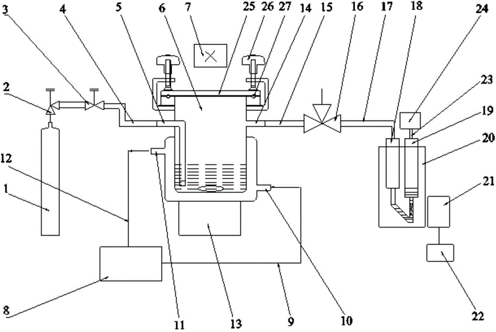
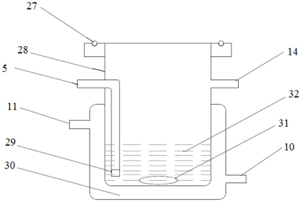
The invention discloses a reaction device for hydrogen production through photocatalytic water splitting. The reaction device comprises a carrier gas steel cylinder, a reaction vessel, a gas metering pool and an infrared counter, wherein the carrier gas steel cylinder, the reaction vessel and the gas metering pool are connected sequentially; the carrier gas steel cylinder is connected with a gas-washing inlet of the reaction vessel through a pressure reducing valve and a flow meter sequentially; a temperature control device is arranged outside the reaction vessel; the gas metering pool comprises a gas metering pool gas charging chamber and a gas metering pool gas discharging chamber, the gas metering pool gas charging chamber is connected with the gas metering pool gas discharging chamber through a V-shaped part and connected with the reaction vessel, and the gas metering pool gas discharging chamber is connected with a gas collection bag; and the infrared counter is used for measuring calibration bubbles produced by the V-shaped part. The invention further discloses a reaction method for hydrogen production through photocatalytic water splitting. The reaction device requires less support equipment, and is simpler, small in occupied space, lower in cost, high in automation degree, low in air-tightness requirement of the device, convenient to operate and maintain and accurate in measurement result.

Description

technical field [0001] The invention relates to the field of clean new energy-hydrogen energy and environmental protection, in particular to a reaction device for hydrogen production by photolysis of water, and a reaction method for production of hydrogen by photolysis of water, which can be widely used in experimental research in the field of photocatalysis. Measure the volume of gas generated in the photocatalytic experimental system and monitor the activity changes of the catalyst in real time. Background technique [0002] At present, the experimental device for hydrogen production by photolysis of water mainly includes six systems: light source system, reaction system, gas circulation control system, vacuum system, online gas sampling system, and chromatographic detection system (gas chromatography). The whole device is serially connected in series through pipelines as the reactor, the first condensate reflux pipe, the gas mixing part, the online sampling part and the s...

Claims


Application Information

Patent Timeline
Patent Type & Authority Patents(China)
IPC IPC(8): C01B3/04
CPCY02E60/36
Inventor 严建中
Owner 湖北洛克泰克仪器股份有限公司
Why Eureka
Try Eureka