Pressurized ash residue treatment technology and system

An ash and slag treatment and ash slag technology, which is applied in the field of pressurized ash and slag treatment processes and systems, can solve the problems of limited ash slag treatment capacity of a drum-type slag cooler, easy leakage of rotating water joints, short residence time, etc. Direct and effective heat method, large fluidized heat exchange effect, good fluidity effect

Active Publication Date: 2014-01-22
江苏晟宜环保科技有限公司
View PDF5 Cites 3 Cited by
  • Summary
  • Abstract
  • Description
  • Claims
  • Application Information

AI Technical Summary

Problems solved by technology

The air-water combined fluidized bed slag cooler adopts the principle of fluidized bed and uses cold air and water-cooled buried pipes to exchange heat with the slag. For example, the composite fluidized bed slag cooler with the patent number ZL200710092413. It has a large processing capacity and is widely used in large-capacity circulating fluidized bed boilers, but it has the following disadvantages: (1) The particle size distribution of the fluidized bed feed is relatively high, and the particle size is generally required to be controlled below 1mm. Large particles or instantaneous large flow of ash enter the fluidized bed slag cooler, and when the fluidization wind is insufficient, it is easy to deposit in the slag cooler, causing coking and blockage; Very easy to wear; (3) The air-cooling ratio is too high, and the heat of the gas after air-cooling and heat exchange can hardly be recovered effectively, and it is easy to affect the environment after being directly discharged. If it is reused, it will need to be cooled to increase energy. (4) When the ash and slag are discharged from the upper system, they are all under pressure, and when entering the cooling slag system to cool down, the operating pressure is normal pressure because of the need for synchronous air cooling. There is a problem that it is difficult to maintain the operating pressure of the upper system; (5) The heat exchange tube bundles are concentrated in the lower section of the slag cooler, the residence time of ash and slag between the heat exchange tube bundles is short, and the ash and slag tends to stay in the cooler under the action of gravity (6) There are multiple partition walls in the slag cooler, which affect the fluidization and heat exchange effects, and there may be coking in the heat exchange chamber between some partition walls
[0004] The drum-type slag cooler does not have high requirements on the particle size of the feed, but with the advancement of large-scale equipment such as circulating fluidized bed boilers, the drum-type slag cooler has limited ash handling capacity, and its operation is easily affected by the fluctuation of coal ash content, which is difficult Magnified defects become more prominent
Compared with the fluidized bed slag cooler, the main operation problems of the drum type slag cooler are: (1) The ash and slag wear is serious, especially the slag inlet needs to be repaired frequently, and the rotating water joint is easy to leak; (2) High power consumption; (3) High temperature pressurized operation is difficult to seal
However, the fluidized bed slag cooler currently has problems such as buried pipe wear, excessive air cooling ratio, easy coking, slag blocking, etc. Therefore, it is necessary to develop a fluidized bed slag cooler with better performance and reduce the operating air volume of the slag cooler , improve its adaptability to feed particle size distribution and its water-cooling ratio, and improve the operation safety and reliability of the slag cooler

Method used


Image

  • Pressurized ash residue treatment technology and system
  • Pressurized ash residue treatment technology and system
  • Pressurized ash residue treatment technology and system

Examples


Embodiment Construction

[0040] The system of the present invention will be further explained below in conjunction with the accompanying drawings.

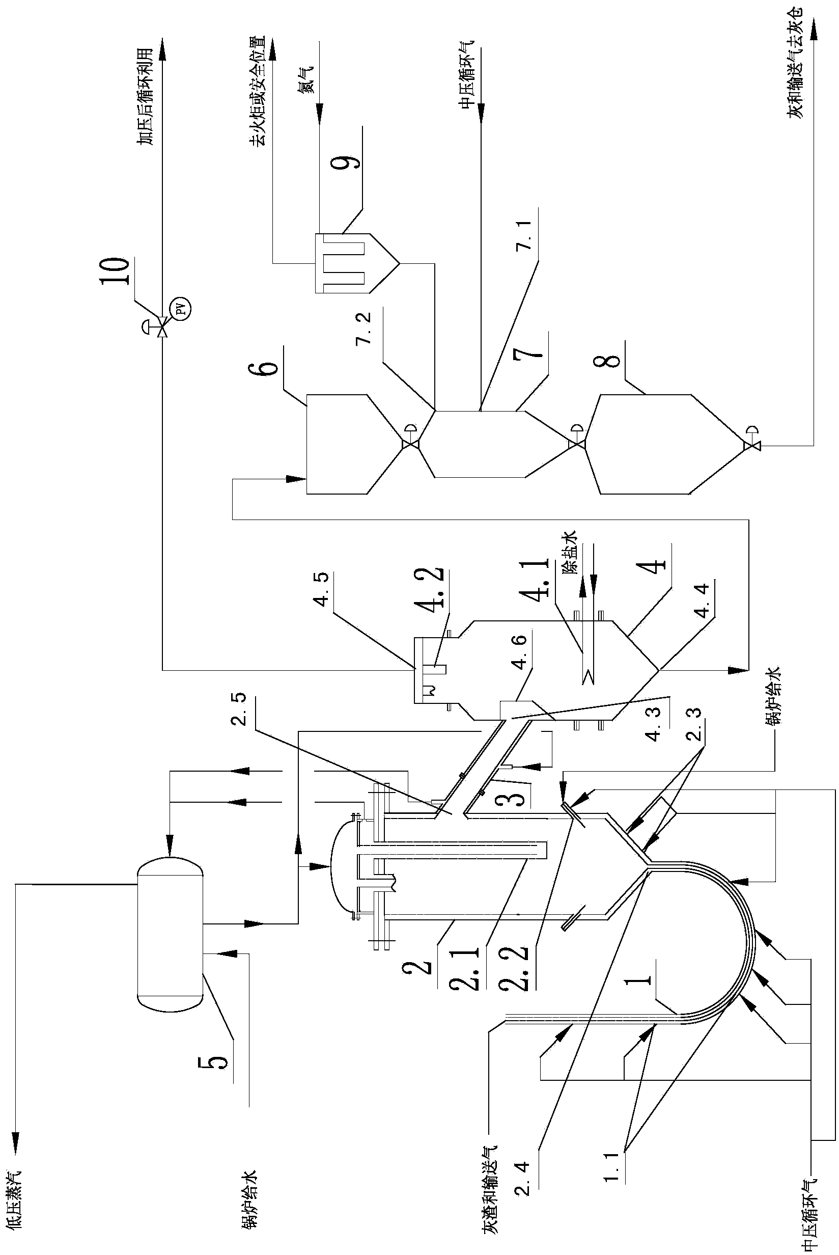
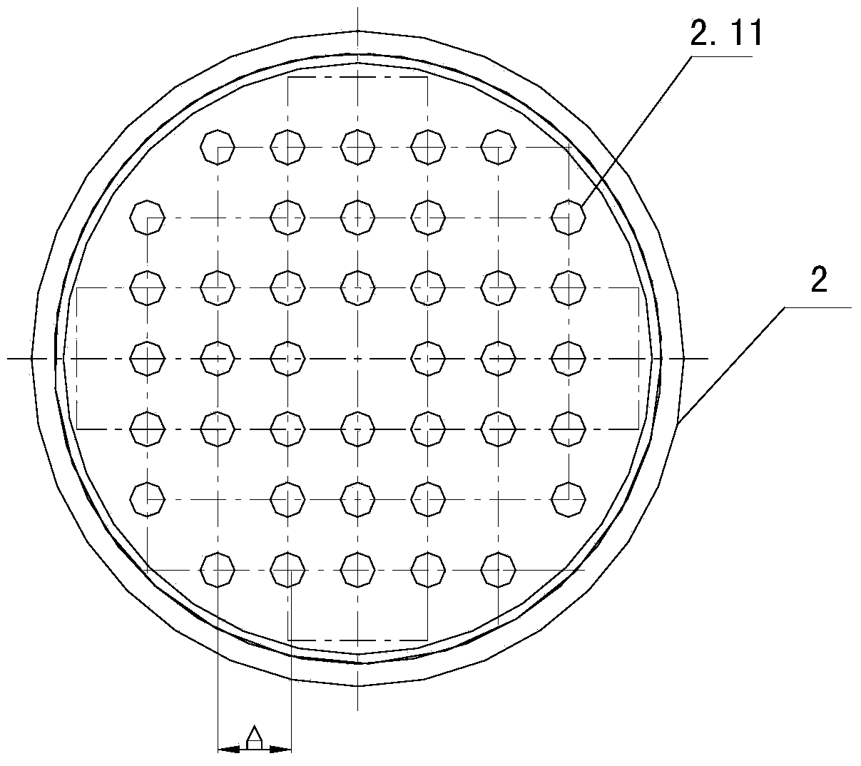
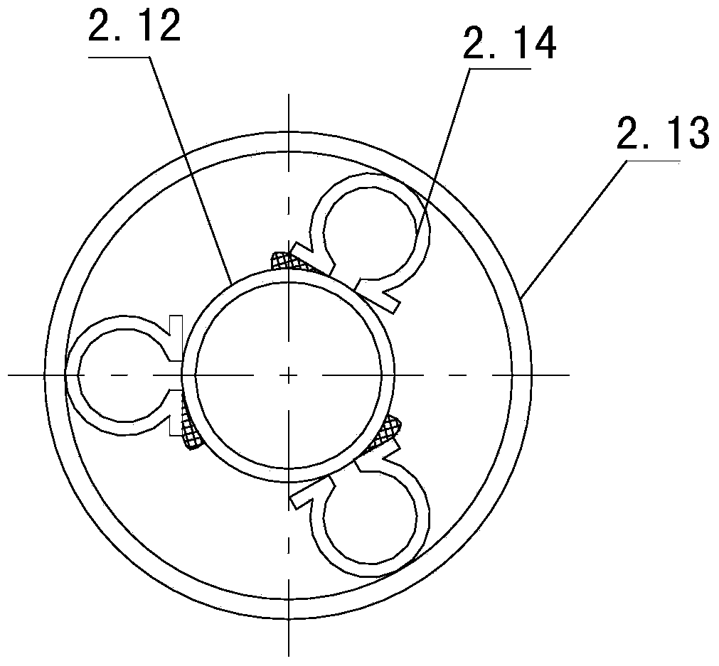
[0041] see figure 1 , the system of the present invention includes a J-shaped dipleg 1, a primary fluidized bed cooler 2, and a secondary cooler 4 connected in sequence, wherein the ash outlet 2.5 of the upper section of the primary fluidized bed cooler 1 passes through a water-cooled clamp The sleeve pipe 3 is connected to the ash inlet 4.3 in the middle section of the secondary cooler 4. The top of the primary fluidized bed cooler 2 is provided with a bayonet-type water-cooled pipe 2.1. The bayonet-type water-cooled pipe 2.1 and the water-cooled jacket pipe 3 Both are connected to the steam drum 5 to form a sealed cooling water circulation route, and the medium and low pressure steam is separated from the steam drum 5; the ash inlet 4.3 of the secondary cooler 4 is provided with a cyclone separator 4.6, and the lower section is provided with a cooling p...


PUM


Abstract

The invention discloses a pressurized ash residue treatment technology and a system thereof, and solves the problems of non-operability of ash residue under pressure, severe pipeline abrasion and low thermal energy recovery efficiency in existing gasification furnaces. The technological method consists of: subjecting high-temperature ash residue to a first stage fluidized bed cooler and a second stage cooler in order to undergo two stage cooling by means of pneumatic conveying, then conducting further depressurization by an ash residue depressurization device and conducting discharge, adopting water cooling heat exchange, and recovering steam by a steam drum. The method involved in the invention has a simple process, the system running cost is low, the investment cost is low, the heat recovery efficiency is high, the water-cooled pipe is not easy to wear, and the ash residue particle size has a wide range of application.

Description

technical field [0001] The invention relates to a process and a system for treating ash and slag, in particular to a process and a system for treating ash and slag under pressure. Background technique [0002] At present, the circulating fluidized bed has been widely used in coal gasification and boiler fields due to its high raw material circulation rate, high heat transfer and mass transfer rate, and is especially suitable for the utilization of low-quality coal in my country. However, the large-scale pressurized circulating fluidized bed technology is not mature at present, and one of the technical problems is how to realize the continuous and stable slag discharge of the circulating fluidized bed. Continuous and stable slag removal is an important means to control the bed thickness, ensure the quality of fluidization and ensure the stable reaction of the furnace. The instability of the slag removal system will lead to fluctuations in the bed height of the fluidized bed, ...

Claims


Application Information

Patent Timeline
Patent Type & Authority Applications(China)
IPC IPC(8): F23C10/24F23C10/18
Inventor 李大振
Owner 江苏晟宜环保科技有限公司
Why Eureka
Try Eureka