Conductive pattern and manufacturing method thereof
A manufacturing method and conductivity technology, which can be used in conductive pattern formation, printed circuit manufacturing, electrical components, etc., can solve problems such as disconnection, and achieve the effect of fine linearity.
- Summary
- Abstract
- Description
- Claims
- Application Information
AI Technical Summary
Problems solved by technology
Method used
Image
Examples
Embodiment 1
[0183] Example 1
[0184] 115 parts by mass of deionized water and 4 parts by mass of LATEMUL E-118B (manufactured by Kao Co., Ltd.: active ingredient 25% by mass) were added to a reaction container equipped with a stirrer, a reflux cooling tube, a nitrogen introduction tube, a thermometer, and a dropping funnel, The temperature was raised to 75°C while blowing nitrogen gas.
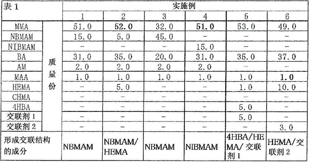
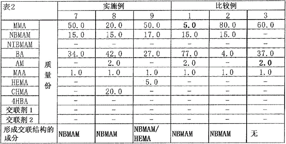
[0185] Under stirring, add 51 parts by mass of methyl methacrylate, 15 parts by mass of N-butoxymethacrylamide, 31 parts by mass of n-butyl acrylate, 2 parts by mass of acrylamide and methyl Vinyl monomer mixture of 1 mass part of acrylic acid, Aqualon KH-1025 (manufactured by Daiichi Kogyo Pharmaceutical Co., Ltd.: active ingredient 25 mass%) 4 mass parts and deionized water 15 mass parts mixed monomer pre-emulsion One part (5 parts by mass), and then 0.1 parts by mass of potassium persulfate were added, and polymerization was carried out for 60 minutes while maintaining the temperature in the reactio...
Embodiment 2~4
[0194] Examples 2 to 4
[0195] Except that the composition of the vinyl monomer mixture was changed to the composition described in the following Table 1, a resin combination for forming a receiving layer with a non-volatile content of 40% by mass was prepared by the same method as that described in Example 1. Objects (I-2) ~ (I-4).
[0196] In addition, the method described in Example 1 was used except that the above-mentioned resin compositions for receiving layer formation (I-2) to (I-4) were respectively used instead of the above-mentioned resin composition for forming a receiving layer (I-1). In the same way, the receiving substrates (II-2) to (II-4) were produced.
Embodiment 5
[0197] Example 5
[0198] 115 parts by mass of deionized water and 4 parts by mass of LATEMUL E-118B (manufactured by Kao Co., Ltd.: active ingredient 25% by mass) were added to a reaction container equipped with a stirrer, a reflux cooling tube, a nitrogen introduction tube, a thermometer, and a dropping funnel, The temperature was raised to 75°C while blowing nitrogen gas.
[0199] Under stirring, to the reaction container, add will comprise 57 parts by mass of methyl methacrylate, 35 parts by mass of butyl acrylate, 2 parts by mass of acrylamide, 1 part by mass of methacrylic acid, 5 parts by mass of 4-hydroxybutyl acrylate A part (5 parts by mass) of monomer pre-emulsion obtained by mixing 4 parts by mass of vinyl monomer mixture, Aqualon KH-1025 (manufactured by Daiichi Kogyo Pharmaceutical Co., Ltd.: active ingredient 25% by mass) and 15 parts by mass of deionized water ), and then 0.1 parts by mass of potassium persulfate was added, and polymerization was carried out ...
PUM
 Abstract
Description
Claims
Application Information
 - R&D
- Intellectual Property
- Life Sciences
- Materials
- Tech Scout
- Unparalleled Data Quality
- Higher Quality Content
- 60% Fewer Hallucinations
Browse by: Latest US Patents, China's latest patents, Technical Efficacy Thesaurus, Application Domain, Technology Topic, Popular Technical Reports.
© 2025 PatSnap. All rights reserved.Legal|Privacy policy|Modern Slavery Act Transparency Statement|Sitemap|About US| Contact US: help@patsnap.com


