Energy-storage radiating sheet and production method thereof
A technology of heat sink and energy storage, applied in semiconductor/solid-state device manufacturing, electrical components, electric solid-state devices, etc., can solve the problems of low thermal conductivity of graphite heat sink, inability to transfer heat to metal, poor interface properties, etc., and achieve excellent Heat dissipation and compressibility, powerful heat dissipation, excellent heat dissipation effect
- Summary
- Abstract
- Description
- Claims
- Application Information
AI Technical Summary
Problems solved by technology
Method used
Image

Examples
Embodiment 1
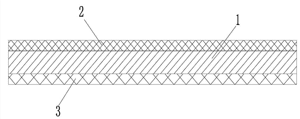
[0035] refer to figure 1 , an energy storage heat sink, comprising a metal layer 1, a thermally conductive silica gel layer 2 is coated on one side of the metal layer 1, and a phase change material layer 3 is coated on the other side of the metal layer 1. Metal layer 1 is copper foil.
[0036] A preparation method for an energy storage heat sink, which comprises the following processing steps in sequence:
[0037] 1) Prepare raw materials: a. Take a piece of copper foil with a thickness of 0.05mm; b. Take thermal conductive silicone base material; c. Take phase change material base material; among them, the thermal conductive silicone base material consists of 5 parts by weight of methyl vinyl silicone , 15 parts by weight of vinyl silica gel, 20 parts by weight of dimethyl silicone oil, 200 parts by weight of spherical alumina powder, 1 part by weight of hydrogen-containing silicone oil, and 0.5 parts by weight of platinum catalyst. The phase change material base material i...
Embodiment 2
[0042] The characteristics of this embodiment are: the metal layer 1 is aluminum foil; the heat-conducting silicone base material is composed of 4 parts by weight of methyl vinyl silicone rubber, 14 parts by weight of vinyl silicone rubber, 19 parts by weight of dimethyl silicone oil, It is prepared by mixing 190 parts by weight of spherical alumina powder, 0.5 part by weight of hydrogen-containing silicone oil, and 1 part by weight of platinum catalyst. The phase change material base material is prepared by mixing 14 parts by weight of polyisobutylene, 9 parts by weight of sliced paraffin, 73 parts by weight of spherical alumina powder, 1 part by weight of coupling agent, and 1 part by weight of dispersant; the metal layer The thickness of 1 is 0.03; the thickness of the thermal silica gel layer is 0.05mm. The thickness of the phase change material layer is 0.05mm.
[0043]After testing: in this embodiment, the thermal conductivity of the aluminum reaches 270w / mk. The the...
Embodiment 3
[0046] The characteristics of this embodiment are: the metal layer is aluminum foil; the heat-conducting silicone base material is composed of 6 parts by weight of methyl vinyl silicone rubber, 16 parts by weight of vinyl silicone rubber, 21 parts by weight of dimethyl silicone oil, 195 parts by weight It is prepared by mixing spherical alumina powder, 1.5 parts by weight of hydrogen-containing silicone oil, and 0.5 parts by weight of platinum catalyst. The phase change material base material is prepared by mixing 16 parts by weight of polyisobutylene, 11 parts by weight of sliced paraffin, 75 parts by weight of spherical alumina powder, 0.5 parts by weight of coupling agent, and 0.5 parts by weight of dispersant; the metal layer The thickness is 0.1; the thickness of the thermal silica layer is 0.05mm. The thickness of the phase change material layer is 0.05mm.
[0047] After testing: in this embodiment, the thermal conductivity of the aluminum reaches 270w / mk. The therma...
PUM
| Property | Measurement | Unit |
|---|---|---|
| Thickness | aaaaa | aaaaa |
| Thermal conductivity | aaaaa | aaaaa |
| Thickness | aaaaa | aaaaa |
Abstract
Description
Claims
Application Information
 - Generate Ideas
- Intellectual Property
- Life Sciences
- Materials
- Tech Scout
- Unparalleled Data Quality
- Higher Quality Content
- 60% Fewer Hallucinations
Browse by: Latest US Patents, China's latest patents, Technical Efficacy Thesaurus, Application Domain, Technology Topic, Popular Technical Reports.
© 2025 PatSnap. All rights reserved.Legal|Privacy policy|Modern Slavery Act Transparency Statement|Sitemap|About US| Contact US: help@patsnap.com