

Method for manufacturing laser array and combiner monolithic integration chip
A laser array and monolithic integration technology, which is applied to lasers, laser components, semiconductor lasers, etc., can solve the problems of reducing the yield of devices and increasing the complexity of device manufacturing, so as to simplify the device manufacturing process and reduce light diffraction loss , The effect of reducing the size of the multiplexer
- Summary
- Abstract
- Description
- Claims
- Application Information
AI Technical Summary
Problems solved by technology
Method used
Image

Examples
Embodiment Construction
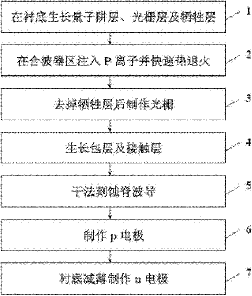
[0026] see figure 1 , is the first embodiment of the present invention, with reference to Figure 3 to Figure 8 As shown, the present invention provides a method for manufacturing a monolithic integrated chip of a laser array and a multiplexer, comprising the following steps:
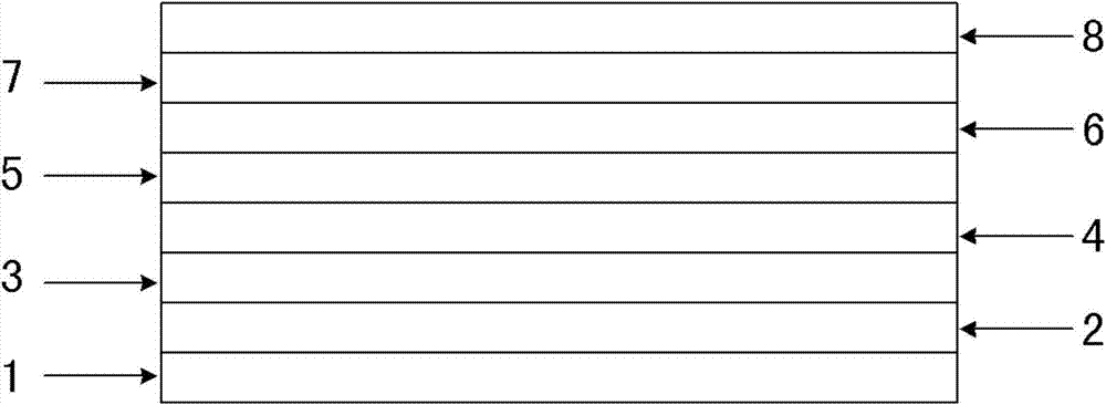
[0027] Step 1: On the n-type InP substrate 1, grow n-type InP buffer layer 2, n-type AlGaInAs cladding layer 3, AlGaInAs multi-quantum well layer 4, p-type AlGaInAs cladding layer 5, InP spacer layer 6, and InGaAsP grating layer 7 sequentially , InP sacrificial layer 8, forming the substrate, such as image 3 , one side of the substrate is the active region A, and the other side is the combiner region D, such as Figure 4 . The AlGaInAs multi-quantum well layer 4 includes more than two AlGaInAs quantum wells and two upper and lower AlGaInAs refractive index gradient layers. There may be no InP spacer layer 6 in the device;
[0028] Step 2: Implant P ions into the InP sacrificial layer 8 in the comb...
PUM
 Abstract
Description
Claims
Application Information