A high-temperature gas atomization rapid cooling system and method

A high-temperature gas, rapid cooling technology, applied in the direction of water shower cooler, energy efficiency improvement, process efficiency improvement, etc., can solve the problems of long cooling process or equipment, difficult rapid acute cooling, and dioxin pollution, etc. Ensure that process conditions are in place and equipment safety, solve technical problems in environmental protection, and shorten the effect of cooling process

Inactive Publication Date: 2015-12-23
GANZHOU JIANGWU NEW TYPE ALLOY MATERIAL
View PDF7 Cites 0 Cited by
  • Summary
  • Abstract
  • Description
  • Claims
  • Application Information

AI Technical Summary

Problems solved by technology

The shortcomings of these cooling methods are that, on the one hand, the temperature of the high-temperature gas is gradually cooled, resulting in a longer cooling process or equipment; on the other hand, due to the obvious gradual temperature cooling gradient, it is difficult Realize rapid and acute cooling, such as conventional methods, it is difficult to directly reduce from 850°C to 180°C within 2 seconds, and quickly skip the temperature range of 300-450°C
[0003] For example, high-temperature gas containing dioxins, in which dioxins decompose at high temperatures (such as over 500 ° C), if conventional cooling methods (such as waste heat boilers) are used in the slow heat exchange cooling process, after 300-450 In the temperature range of ℃, the reverse reaction occurs and dioxins are automatically synthesized, which brings serious secondary pollution to the environment. It is also a problem that many plastics (such as medical waste) are incinerated at high temperatures to cause dioxin pollution.

Method used


Image

  • A high-temperature gas atomization rapid cooling system and method

Examples


Embodiment 1

[0039] Embodiment 1: Prevention and treatment system of dioxin pollution

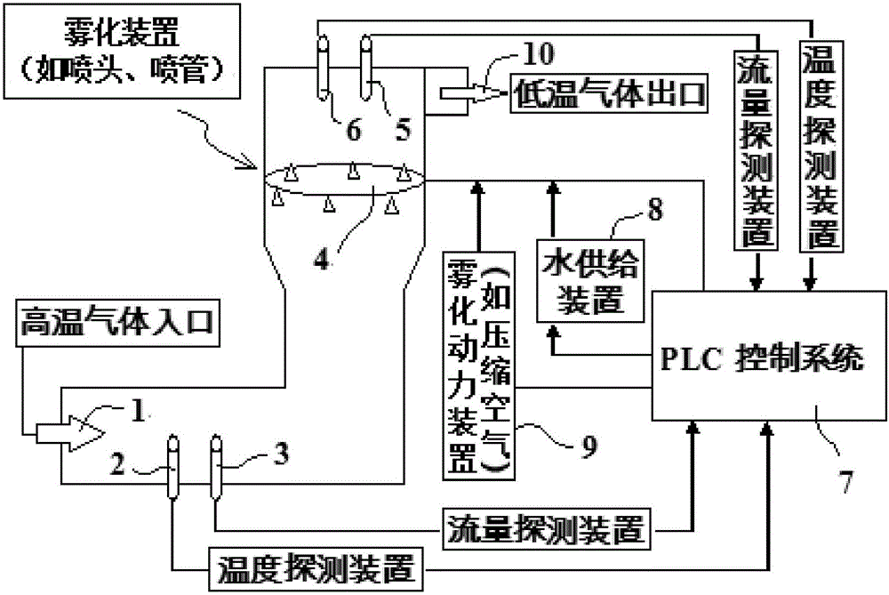
[0040] As shown in the figure, the high-temperature gas atomization rapid cooling system of the present invention includes: high-temperature gas inlet 1, temperature probe 2, gas flow probe 3, atomization nozzle 4, temperature probe 5, gas flow probe 6, PLC control system 7, Cooling water supply device 8 , atomization power device (such as compressed air) 9 , low-temperature gas outlet 10 .

[0041] The high-temperature gas generated after the high-temperature incineration of plastic materials passes through the high-temperature gas inlet 1 (for example, the temperature is 800°C), and through the subsequent fan suction (such as the fan behind the low-temperature gas outlet 10), the gas is guided to flow to the cooling tower; the high-temperature gas passes through the temperature probe 2 and the gas flow probe 3, respectively measure the temperature (such as temperature 800°C) and flow (Q); quickly tr...


PUM


Abstract

The invention discloses a high-temperature air atomization and shock cooling system and a method. High-temperature air flows to the top of a cooling tower from the bottom of the cooling tower by an air guide device; a temperature detection device and a flow detection device are arranged at the bottom of the cooling tower; cooling water is sprayed in from the periphery of the upper part in the cooling tower, the atomization is performed for absorbing heat, and the high-temperature air is cooled; the amount of the cooling water required by the atomization for cooling is calculated by using a PLC (Programmable Logic Controller) control system; the high-temperature air is subjected to shock cooling to a preset temperature, the sprayed water is changed to steam which is pumped out from the top end after cooling; another temperature detection device and another flow detection device are arranged at the top of the cooling tower and can be used for feeding back to the PLC control system so as to realize the automatic fine water amount adjusting. The system has the characteristics that the high-temperature air can be subjected to the shock cooling, and the fast cooling aim can be realized by water atomization for the cooling, so that a certain temperature region can be fast crossed, the cooling can be realized with a short flow, the occupying area is small, the secondary pollution is avoided and the like.

Description

technical field [0001] The invention relates to a high-temperature gas atomization rapid cooling system and method, belonging to the technical field of environmental protection. Background technique [0002] At present, many fields such as metallurgy and chemical industry usually produce high-temperature gas, which needs to be cooled before being discharged or recycled. Most of the cooling methods are heat exchange with waste heat boilers, air cooling, water and oil. The shortcomings of these cooling methods are that, on the one hand, the temperature of the high-temperature gas is gradually cooled, resulting in a longer cooling process or equipment; on the other hand, due to the obvious gradual temperature cooling gradient, it is difficult To achieve rapid and acute cooling, it is difficult to achieve a direct drop from 850°C to 180°C within 2 seconds by conventional methods, and quickly skip the temperature range of 300-450°C. These deficiencies bring great difficulty to p...

Claims


Application Information

Patent Timeline
Patent Type & Authority Patents(China)
IPC IPC(8): F28C1/02F28F27/00F27D17/00F23J15/06
CPCY02P10/25
Inventor 尹家军
Owner GANZHOU JIANGWU NEW TYPE ALLOY MATERIAL
Why Eureka
Try Eureka