Coherent light detection system and method for optical fiber delay line phase control

A fiber delay line and phase control technology, applied in the field of optical communication, can solve problems such as phase change, optical path difference, and detection result dependence, so as to achieve the effect of improving performance, improving certainty, and enhancing application value

Active Publication Date: 2014-02-12
GUILIN UNIV OF ELECTRONIC TECH
View PDF5 Cites 17 Cited by
  • Summary
  • Abstract
  • Description
  • Claims
  • Application Information

AI Technical Summary

Problems solved by technology

However, in the process of conventional laser communication signal transmission, there is an optical path difference, which will inevitably introduce a certain phase change. When the laser frequency is consistent, the final detection result will depend on the phase change.

Method used


Image

  • Coherent light detection system and method for optical fiber delay line phase control
  • Coherent light detection system and method for optical fiber delay line phase control
  • Coherent light detection system and method for optical fiber delay line phase control

Examples


Embodiment 1

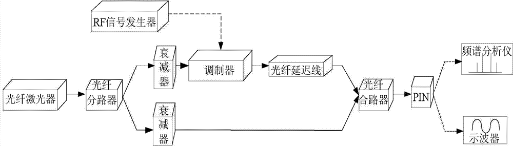
[0027] A coherent optical detection system with fiber delay line phase control such as figure 2 As shown, it is mainly composed of fiber laser, fiber splitter, modulator, fiber delay line, polarization maintaining fiber coupler and photodetector. Wherein the output end of the fiber laser is connected with the input end of the fiber splitter. The first output end of the fiber optic splitter is connected to one input end of the modulator, the other input end of the modulator is connected to an external RF signal generator, and the output end of the modulator is connected to a polarization maintaining fiber coupler through a fiber delay line an input terminal of . The second output end of the fiber splitter is directly connected to the other input end of the polarization maintaining fiber coupler. The output end of the polarization maintaining fiber coupler is connected with a photodetector.

[0028] The laser signal generated by a single-frequency laser with a center frequen...

Embodiment 2

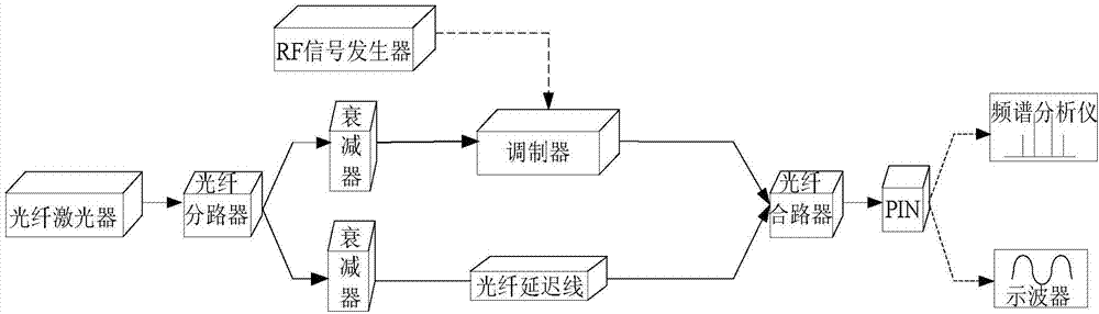
[0038] A coherent optical detection system with fiber delay line phase control such as image 3As shown, it is mainly composed of fiber laser, fiber splitter, modulator, fiber delay line, fiber combiner and photodetector. Wherein the output end of the fiber laser is connected with the input end of the fiber splitter. The first output end of the fiber optic splitter is connected to one input end of the modulator, the other input end of the modulator is connected to an external RF signal generator, and the output end of the modulator is directly connected to an input end of the fiber optic combiner . The second output end of the optical fiber splitter is connected to the other input end of the optical fiber combiner through an optical fiber delay line. The output end of the optical fiber combiner is connected with a photodetector.

[0039] The laser signal generated by a single-frequency laser with a center frequency of 1550nm is divided into two paths through a 1×2 fiber spl...


PUM


Abstract

The invention discloses a coherent light detection system and method for optical fiber delay line phase control. The output end of an optical fiber laser device is connected with the input end of an optical fiber branching unit. A first output end of the optical fiber branching unit is connected with an input end of a modulator. The other input end of the modulator is connected with an external RF signal generator. The output end of the modulator is connected with an input end of an optical fiber combiner. A second output end of the optical fiber branching unit is connected with the other input end of the optical fiber combiner. An optical fiber delay line is connected in series between the output end of the modulator and an input end of the optical fiber combiner, or the optical fiber delay line is connected in series between the second output end of the optical fiber branching unit and the other input end of the optical fiber combiner. The output end of the optical fiber combiner is connected with the input end of a photoelectric detector. According to the coherent light detection system and method for optical fiber delay line phase control, phase control can be achieved through the optical fiber delay line, and phase difference between reference light and a signal light branch is compensated, so that receiving sensitivity, the signal to noise ratio and system output stability are improved.

Description

technical field [0001] The invention relates to the field of optical communication, in particular to a coherent light detection system and method for optical fiber delay line phase control. Background technique [0002] The rapid development of laser and optical fiber technology has enabled coherent optical communication to achieve another important leap. It has been widely used not only in the field of optical communication, but also in other fields such as sensing and signal processing. Due to the advantages of good filtering performance, high frequency band utilization, and high receiving sensitivity, it becomes an effective means to meet the high requirements of communication terminals and solve the bottleneck of optical communication. Coherent light detection systems (see figure 1 ) whose output signal satisfies: The condition for the establishment of this formula is that the wavefronts of signal light and reference light must maintain the same frequency and phase re...

Claims


Application Information

Patent Timeline
Patent Type & Authority Applications(China)
IPC IPC(8): G01J9/02
Inventor 何宁龚雨心黄灵鹭廖欣冯太琴张雷
Owner GUILIN UNIV OF ELECTRONIC TECH
Why Eureka
Try Eureka