Non-magnetic heating temperature control system

A temperature control system and temperature controller technology, applied in the direction of temperature control, control/regulation system, non-electric variable control, etc. Noise interference, good temperature stability, and the effect of avoiding magnetic field interference

Inactive Publication Date: 2014-02-12
HARBIN ENG UNIV
6 Cites 15 Cited by

AI-Extracted Technical Summary

Problems solved by technology

Alternating current heating will introduce magnetic noise, intermittent electric heating has poor temperature stability and will produce temperature gradients, thermal airflow heating speed is slow, airflow fluctuatio...

Method used

[0020] As shown in Figure 1, non-magnetic heating temperature control system. It includes a laser 1, a 1×4 optical splitter 3, an atomic heating chamber 6 and a temperature controller 8. Laser 1 is a semiconductor laser with a wavelength of 850nm and a maximum optical power of 3W, and has a pigtail 2 output, and the maximum output optical power is 2W. The main beam laser emitted by the laser 1 enters the 1×4 optical splitter 3 through the pigtail 2, and the splitting ratio of the 1×4 optical splitter 3 is 25:25:25:25, that is, the four beams in the pigtail 4 The beam laser light power is equal. The pigtail 4 passes through the insulation layer 5 and the atomic heating chamber 6, and is fixed in the middle of the side wall of the atomic heating chamber 6. The four pigtails are adjacent to each other at 90° and surround the atomic gas chamber 10 for heating, so as to ensure the minimum temperature gradient in the effective working area . In the atomic heating chamber 6, a non-magnetic platinum resistor 11 is used as a non-magnetic temperature sensor, placed directly under the atomic gas chamber 10, and the temperature of the atomic gas chamber 10 is collected in real time. The temperature controller 8 receives the temperature collected by the non-magnetic platinum resistor 11 through the wire 7 and uses the neural network artificial intelligence PID to adjust the output power of the laser 1 through the single-core shielded signal line 9, thereby achieving the purpose of controlling the temperature of the atomic gas chamber 10. The temperature control accuracy reaches 0.5°C. At this time, a closed-loop temperature control system is formed.
[0021] Since the atomic gas chamber 10 needs to work in a nonmagnetic environment, the atomic heating chamber 6 is made of nonm...

Abstract

The invention relates to a non-magnetic heating temperature control system, in particular to the non-magnetic heating temperature control system which is used for an atom magnetometer system and utilizes laser to heat an atomic air chamber. The non-magnetic heating temperature control system comprises a laser, a 1*4 optical divider, an atom heating chamber and a temperature controller, and is characterized in that the laser and the 1*4 optical divider are connected through a tail fiber, the 1*4 optical divider and the atom heating chamber are connected through a tail fiber, and the temperature controller and the laser are connected through a single-core shielding signal line. An enough span exists between the electrical part, which can generate a disturbing magnetic field of the laser and the temperature controller and the atom heating chamber, and therefore the situation that a working area of the atomic air chamber generates magnetic field interference is avoided. A laser heating mode is adopted, the influence of introducing magnetic noise is avoided in the same way, the heating speed is high, a three-wire non-magnetic platinum resistor is used as the temperature sensor, the accuracy of measuring the temperature is guaranteed, and meanwhile the interference of the magnetic noise is avoided.

Application Domain

Temperatue control

Technology Topic

Magnetic noiseControl system +11

Image

  • Non-magnetic heating temperature control system

Examples

  • Experimental program(1)

Example Embodiment

[0018] The present invention will be further described below in conjunction with the drawings.
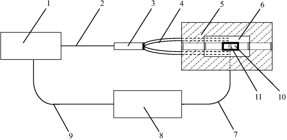
[0019] A non-magnetic heating temperature control system includes a laser 1, a 1×4 optical splitter 3, an atomic heating chamber 6 and a temperature controller 8. Laser 1 is a semiconductor laser with a wavelength of 850nm, a maximum optical power of 3W, and a pigtail 2 output, with a maximum output optical power of 2W. The main beam laser from laser 1 enters 1×4 optical splitter 3 through pigtail 2. The splitting ratio of 1×4 optical splitter 3 is 25:25:25:25, that is, four beams in pigtail 4 The beam laser light power is equal. The pigtail 4 passes through the insulation layer 5 and the atomic heating chamber 6, and is fixed at the middle position of the side wall of the atomic heating chamber 6. The four pigtails are adjacent to each other at 90° and surround the atomic gas chamber 10 for heating, ensuring the minimum temperature gradient in the effective working area . The atomic heating chamber 6 is a cylindrical axial hollow and transparent structure, with an outer diameter of 56mm, an inner diameter of 36mm, and a length of 50mm, made of non-magnetic material silicon carbide. The atomic heating chamber 6 is placed at the center of the thermal insulation layer 5. The thermal insulation layer 5 is a rectangular parallelepiped axially hollow and transparent structure made of polystyrene foam with low thermal conductivity. The atomic gas chamber 10 is a cylinder and is placed in the center of the atomic heating chamber 6. The central points of the thermal insulation layer 5, the atomic heating chamber 6 and the atomic gas chamber 10 are all located on the same straight line. A non-magnetic platinum resistance 11 is used as a non-magnetic temperature sensor in the atomic heating chamber 6 and is placed directly below the atomic gas chamber 10. The non-magnetic platinum resistor 11 is welded by high temperature spot welding, and the maximum remanence is better than 5pT. The temperature controller 8 receives the temperature collected by the non-magnetic platinum resistor 11 through the wire 7, and uses the neural network artificial intelligence PID to adjust the output power of the laser 1 through the single-core shielded signal line 9, so as to achieve the purpose of controlling the temperature of the atomic gas chamber 10. The temperature control accuracy reaches 0.5℃.
[0020] Such as figure 1 Shown, non-magnetic heating temperature control system. Including laser 1, 1×4 optical splitter 3, atomic heating chamber 6 and temperature controller 8. Laser 1 is a semiconductor laser with a wavelength of 850nm, a maximum optical power of 3W, and a pigtail 2 output, with a maximum output optical power of 2W. The main beam laser from laser 1 enters 1×4 optical splitter 3 through pigtail 2. The splitting ratio of 1×4 optical splitter 3 is 25:25:25:25, that is, four beams in pigtail 4 The beam laser light power is equal. The pigtail 4 passes through the insulation layer 5 and the atomic heating chamber 6, and is fixed at the middle position of the side wall of the atomic heating chamber 6. The four pigtails are adjacent to each other at 90° and surround the atomic gas chamber 10 for heating, ensuring the minimum temperature gradient in the effective working area . A non-magnetic platinum resistance 11 is used as a non-magnetic temperature sensor in the atomic heating chamber 6, which is placed directly under the atomic gas chamber 10 to collect the temperature of the atomic gas chamber 10 in real time. The temperature controller 8 receives the temperature collected by the non-magnetic platinum resistor 11 through the wire 7, and uses the neural network artificial intelligence PID to adjust the output power of the laser 1 through the single-core shielded signal line 9, so as to achieve the purpose of controlling the temperature of the atomic gas chamber 10. The temperature control accuracy reaches 0.5℃. At this time, a closed-loop temperature control system is formed.
[0021] Since the atomic gas chamber 10 needs to work in a non-magnetic environment, the atomic heating chamber 6 is made of non-magnetic material silicon carbide, and the maximum remanence is better than 5pT. This material has the characteristics of high temperature resistance, good thermal conductivity, corrosion resistance, etc., but also has a certain mechanical strength and is easier to process. The atomic heating chamber 6 is a cylindrical axial hollow and transparent structure with an outer diameter of 56 mm, an inner diameter of 36 mm, and a length of 50 mm. The atomic gas chamber 10 is a cylinder, and is placed in the center of the atomic heating chamber 6. Finally, in order to achieve better insulation performance, an insulation layer 5 is added to the outer layer of the atomic heating chamber 6. The thermal insulation layer 5 is a rectangular parallelepiped axially hollow and transparent structure, and is made of polystyrene foam with low thermal conductivity, ensuring that the internal temperature of the atomic heating chamber 6 has good uniformity. The central points of the thermal insulation layer 5, the atomic heating chamber 6 and the atomic gas chamber 10 are all located on the same straight line.
[0022] In order to monitor the temperature of the atomic gas chamber 10 without introducing magnetic noise, a three-wire non-magnetic platinum resistance 11 is used as a non-magnetic temperature sensor. The probe of the non-magnetic platinum resistance 11 is made of pure platinum, the wire is pure copper, and both are non-ferromagnetic materials. Welding by means of high temperature spot welding minimizes the remanence of the sensor. In actual application, the non-magnetic platinum resistor 11 transmits the current real-time temperature of the atomic gas chamber 10 as a feedback signal to the temperature controller 8 to display and adjust the output power of the laser 1.

PUM

PropertyMeasurementUnit
Wavelength850.0nm
Outer diameter56.0mm
The inside diameter of36.0mm

Description & Claims & Application Information

We can also present the details of the Description, Claims and Application information to help users get a comprehensive understanding of the technical details of the patent, such as background art, summary of invention, brief description of drawings, description of embodiments, and other original content. On the other hand, users can also determine the specific scope of protection of the technology through the list of claims; as well as understand the changes in the life cycle of the technology with the presentation of the patent timeline. Login to view more.

Similar technology patents

Air channel heating device

Owner:ZHENJIANG DONGFANG ENERGY SAVING EQUIP

Process for producing pet food by utilizing fresh meat grouting technology

PendingCN111184241Aguaranteed liquidityFast heating
Owner:蛙牌宠物(湖北)股份有限公司

Classification and recommendation of technical efficacy words

  • fast heating
  • Avoid Magnetic Interference

Quick-drying and repairing refractory material

InactiveCN102674851AGood binding performanceFast heating
Owner:DALIAN JINZHOU JINAN REFRACTORINESS CO LTD

Method of operating a spark ignition internal combustion engine

ActiveUS20080228378A1fast heatinggood smoothness of run
Owner:DAIMLER AG
Why Eureka
Try Eureka