Vacuum coating machine

The technology of a vacuum coating machine and a vacuum cover is applied in the field of machinery, which can solve the problems such as the decrease of the uniformity of the film on the surface of the coated workpiece, and achieve the effects of improving the heating condition, increasing the loading quantity, and increasing the loading quantity.

Active Publication Date: 2014-02-19
ZHEJIANG XINGXING TECH CO LTD
View PDF4 Cites 9 Cited by
  • Summary
  • Abstract
  • Description
  • Claims
  • Application Information

AI Technical Summary

Problems solved by technology

However, the problems of the workpiece three-dimensional rotating bracket of the vacuum coating machine with this structure are: 1. There is still a large space not fully utilized when the rotating bracket revolves, and the production capacity of the workpiece coating can be further improved; 2. The direction of the rotation axis of the rotating bracket The distances between multiple workpieces and the evaporation source are different. The workpieces close to the evaporation source block the workpieces far away from the evaporation source, and the evaporation source needs to provide more coating materials; 3. Whether it is revolution, rotation, or rotation, position the workpiece on the rotating shaft , resulting in different degrees of shaking of the rotating shaft during the rotation process, thereby reducing the uniformity of the film on the surface of the plated workpiece

Method used


Image

  • Vacuum coating machine
  • Vacuum coating machine
  • Vacuum coating machine

Examples


Embodiment 1

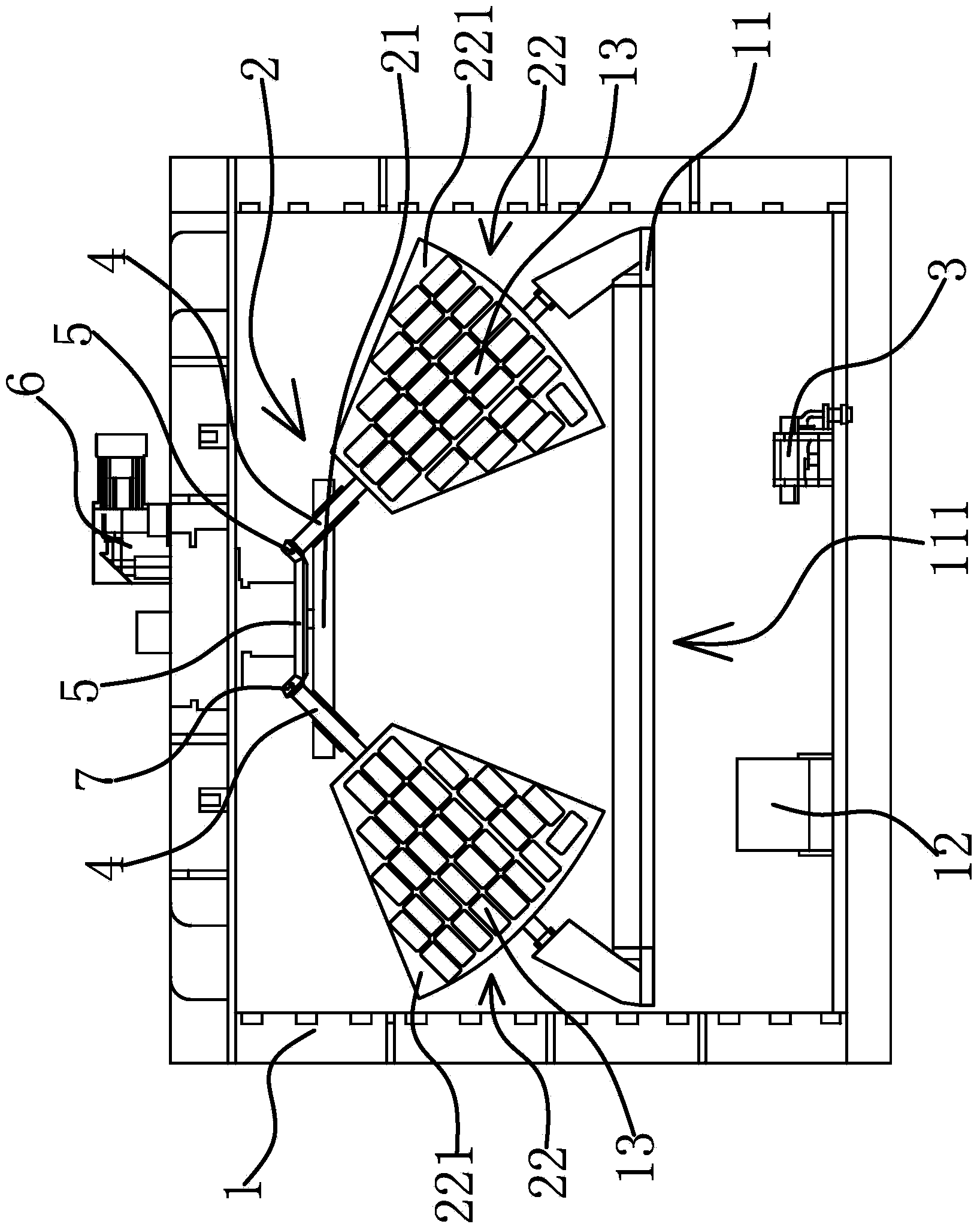
[0031] The vacuum coating machine includes a vacuum cover 1, a vacuum system, an umbrella stand 2, an evaporation source 3 and a driving mechanism.

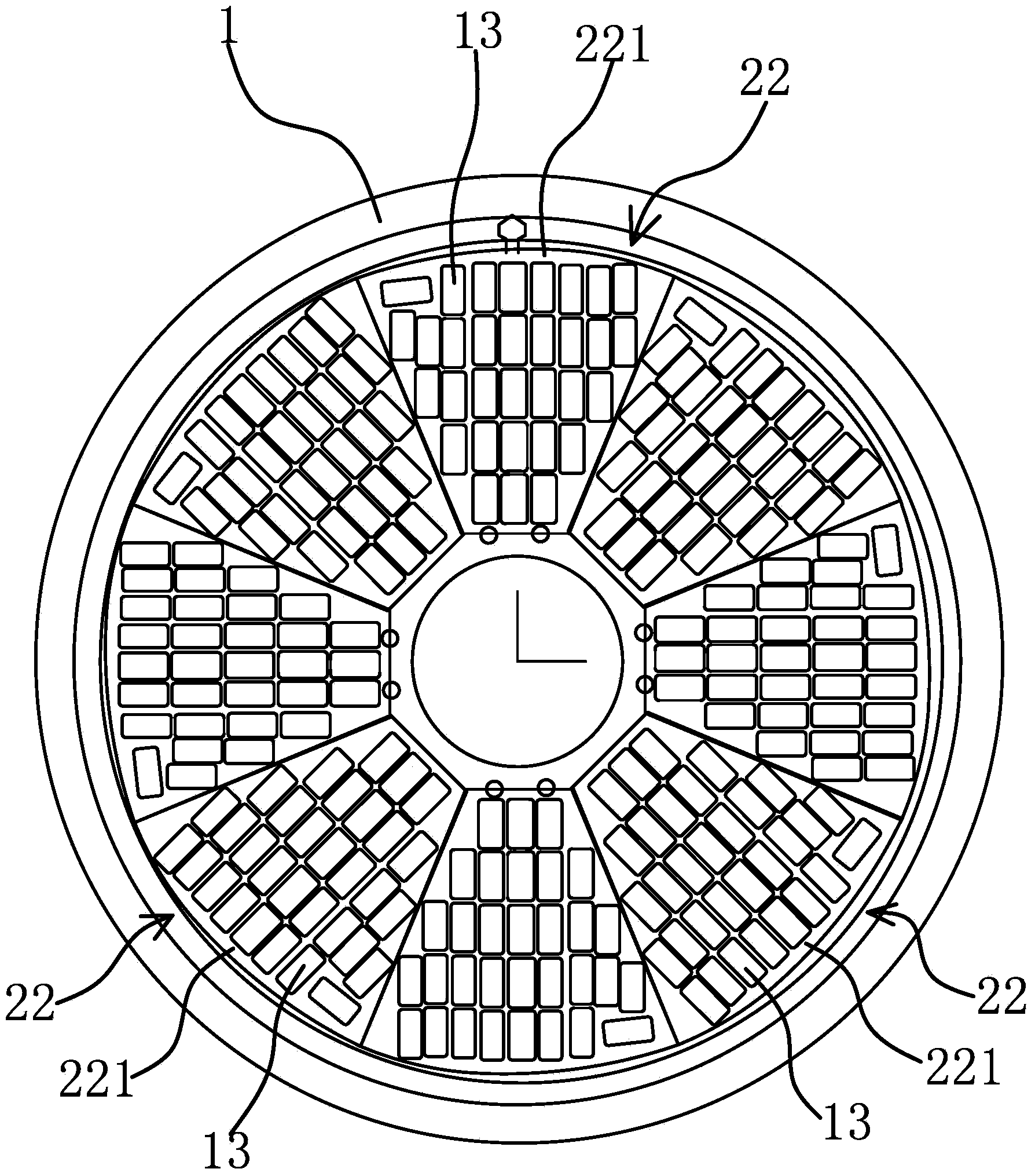
[0032] Specifically, as figure 1 As shown, the umbrella stand 2 includes a turntable 21 and a workpiece holder 22, the turntable 21 is connected with the vacuum cover 1 through a transmission shaft, and the transmission shaft can drive the rotating shaft to rotate in a circumferential direction. likefigure 1 and figure 2 As shown, the workpiece holder 22 is distributed in an umbrella shape along the circumferential direction of the turntable 21 , and the inclination angle of the workpiece holder 22 relative to the turntable 21 is less than 90°. A rotating shaft 4 is respectively fixed on the upper end of the workpiece holder 22, and the rotating disk 21 has mounting holes for the rotating shaft 4 to pass through, and the rotating shaft 4 is respectively packed into the corresponding mounting holes.

[0033] The driving mechani...

Embodiment 2

[0039] The technical solution in this embodiment is basically the same as the technical solution in Embodiment 1, the difference is that, as Figure 4 As shown, in the present embodiment, the drive mechanism includes a friction track 8 and a drive motor 6, the friction track 8 is circumferentially distributed on the inner wall of the vacuum cover 1, the drive motor 6 is connected to the turntable 21 through a transmission pair, and the other end of the workpiece holder 22 is provided with a Rotating shaft 1 4 centerline is located on the same straight line as rotating shaft 2 9, the end of rotating shaft 2 9 is fixedly connected with friction wheel 10, friction wheel 10 can roll in the friction track 8 to make the substrate rotate around the center line of rotating shaft 4 and rotating shaft 2 9 . During the rotation of the workpiece holder 22 with the turntable 21, the second shaft 9 moves circumferentially along the friction track 8, and the friction wheel 10 fixed on the se...

Embodiment 3

[0041] The technical solution in this embodiment is basically the same as the technical solution in Embodiment 1. The difference is that in this embodiment, the drive mechanism includes a rotation motor and a revolution motor, and the revolution motor is connected to the turntable 21 through a transmission pair, and the rotation motors are respectively Link to each other with rotating shaft one 4 through transmission pair. The autorotation motor and the revolution motor respectively drive the autorotation and revolution of the workpiece rack 22, and the precise control of the autorotation and revolution of the workpiece rack 22 can be realized through the automatic control equipment.


PUM


Abstract

The invention provides a vacuum coating machine, belongs to the technical field of machinery, and solves the problem of low production capacity of a conventional vacuum coating machine. The vacuum coating machine comprises a vacuum cover and a vacuum system used for keeping the inside of the vacuum cover in a vacuum state, wherein an umbrella frame and a steaming source are arranged in the vacuum cover; the umbrella frame comprises a rotary plate capable of circumferentially rotating and a plurality of workpiece frames; the workpiece frames are connected with the rotary plate through the first rotary shafts of the workpiece frames respectively and are distributed in an umbrella shape in the circumferential direction of the rotary plate. The vacuum coating machine also comprises a drive mechanism capable of rotating around the central lines of the first rotary shafts while driving the workpiece frames to rotate in the circumferential direction of the rotary plate. According to the vacuum coating machine, a structure that the workpiece frames are distributed in the umbrella shape in the circumferential direction of the rotary plate is adopted, so that the space occupied by the umbrella frame is reduced and the receptor area of the workpiece frames to steaming materials is enlarged; the front and rear surfaces of the workpiece frames are all capable of loading workpieces to be coated, so that the loading quantity of the workpiece frames is increased. The vacuum coating machine is higher in production capacity and better in economic benefit.

Description

technical field [0001] The invention belongs to the technical field of machinery and relates to a vacuum coating machine. Background technique [0002] With the development of science and technology, the performance of display screens of electronic equipment is continuously improved, and touch screens controlled by direct touch of human hands appear. During actual use, the display screen is easily contaminated with external dust and other dirt, and the touch screen is more likely to leave fingerprints or scratches after being touched. In order to improve the wear resistance and dirt resistance of the display screen, a layer of high wear resistance and anti-fingerprint coating is usually applied on the surface of the display screen by means of vacuum coating. [0003] Vacuum coating is a technology that separates the atoms of the material in the vacuum chamber from the heating source and hits them on the surface of the object to be plated, thereby forming a thin film. The e...

Claims


Application Information

Patent Timeline
IPC IPC(8): C23C14/24C23C14/50
Inventor 王先玉夏永光
Owner ZHEJIANG XINGXING TECH CO LTD
Why Eureka
Try Eureka