Heat tube type photovoltaic photo-thermal member

A heat pipe type, photovoltaic technology, applied in the field of solar energy utilization, can solve the problems of hindering heat transfer, reducing heat conversion efficiency, unable to fully utilize sunlight, etc., to achieve the effect of improving heat conversion efficiency and reducing air interlayers

Inactive Publication Date: 2014-02-19
SUN YAT SEN UNIV
View PDF8 Cites 24 Cited by
  • Summary
  • Abstract
  • Description
  • Claims
  • Application Information

AI Technical Summary

Problems solved by technology

[0004] China's authorized invention patent "Integrated Solar Photovoltaic Photothermal Panel" (ZL201010264858.0) discloses a photovoltaic photothermal integrated structure, which has the following defects: the upper part of the photovoltaic module is combined with the glass cover, and the lower part is connected with the solar There is a certain thickness of air layer between the heat absorbing plates. Because the thermal conductivity of air is very low, the air layer largely hinders the transfer of heat and reduces the heat conversion efficiency of the entire system.
However, the common disadvantages of these two photovoltaic-thermal integrated structures are: due to the limitation of the material of the solar heat-absorbing plate, the photovoltaic-thermal systems of these two structures can only absorb part of the solar spectrum, and cannot realize Make full use of sunlight

Method used


Image

  • Heat tube type photovoltaic photo-thermal member
  • Heat tube type photovoltaic photo-thermal member
  • Heat tube type photovoltaic photo-thermal member

Examples


Embodiment Construction

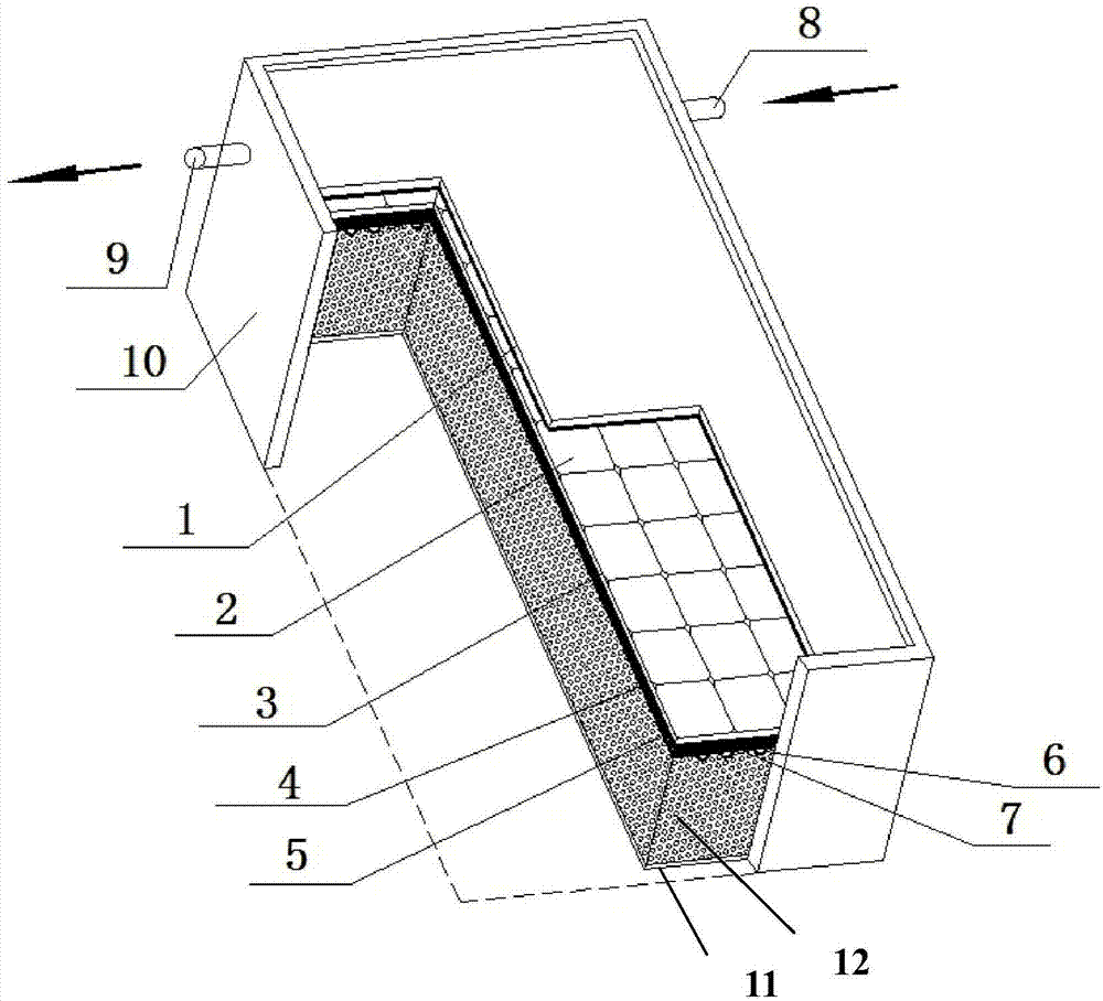
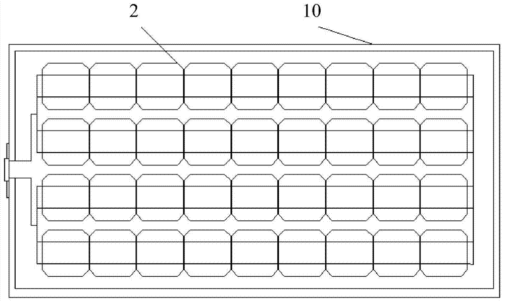
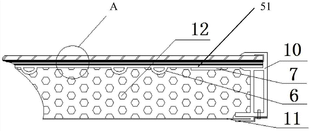
[0029] like Figure 1~4 As shown, it is a heat pipe type photovoltaic photothermal component of the present invention, which includes a glass cover plate 1, solar cells 2 connected in series and parallel rows, a packaging material TPT3, and a solar spectrum selective absorption coating for absorbing the infrared band of the solar spectrum. Layer 4, tube plate heat absorbing plate 5, heat preservation layer 12 and profile frame 10, wherein the solar cells 2 are solar cells composed of monocrystalline silicon connected in series and parallel. The glass cover plate 1, the solar battery sheet 2, the packaging material TPT3 and the solar spectrum selective absorption coating 4 are sequentially laminated and bonded from top to bottom; The heat collecting tube 6 on the plate surface is composed of the heat collecting tube 6. The cross section of the heat collecting tube 6 is a downwardly protruding arc, which together with the plate body 51 forms a channel for the flow of the cooling...


PUM


Abstract

The invention discloses a heat tube type photovoltaic photo-thermal member which comprises a glass cover plate, solar battery pieces, a packaging material TPT, a solar spectrum selective absorption coating, a tube plate type heat absorption plate, a heat insulation layer and an outer section frame, wherein the solar battery pieces are in series connection and parallel connection in rows, and the solar spectrum selective absorption coating is used for absorbing the infrared wave band of the solar spectrum; the glass cover plate, the solar battery pieces, the TPT packaging material and the solar spectrum selective absorption coating are sequentially laminated and attached from top to bottom; the tube plate type heat absorption plate is mainly formed by a plate body and a heat collection tube arranged on the lower surface of the plate body, the cross section of the heat collection tube is of a downwards protruding arc shape; the upper surface of the plate body is fixed on the lower surface of the solar spectrum selective absorption coating to form a strong platy body; the heat insulation layer covers the lower surface of the tube plate type heat absorption plate and is supported by a base plate, and the heat insulation layer and the strong platy body are jointly fixed in the outer section frame. By the adoption of the heat tube type photovoltaic photo-thermal member, an air interlayer is decreased, and therefore heat conversion efficiency is enhanced; in addition, because the heat collection tube is of the arc shape, the contact area can be enlarged, pressure-bearing can be enhanced, and it can be guaranteed that the member runs stably for a long time.

Description

technical field [0001] The invention belongs to the technical field of solar energy utilization, and in particular relates to a heat pipe type photovoltaic photothermal component. Background technique [0002] The development and utilization of solar energy is an important way to save fossil energy and protect the environment, among which solar thermal utilization and solar photovoltaic power generation technologies have been developed rapidly. In the utilization of solar heat, the utilization of medium and low temperature is mainly used to achieve the purposes of heating, drying and hot water. Solar photovoltaic power generation technology is to directly convert sunlight into electrical energy. In the current photovoltaic market, crystalline silicon solar cells are the main technology, and its technology is also becoming mature. [0003] Crystalline silicon solar cells are mainstream photovoltaic power generation products, but limited by the material properties of Si, the ...

Claims


Application Information

Patent Timeline
Patent Type & Authority Applications(China)
IPC IPC(8): F24J2/24F24J2/48H01L31/0525H02S40/44F24S10/70
CPCY02E10/44Y02E10/50Y02E10/60
Inventor 梁宗存郑庆琳
Owner SUN YAT SEN UNIV
Why Eureka
Try Eureka