
Micro thermal optoelectronic system cooled based on loop heat pipe principle

A micro-thermal photoelectric, loop heat pipe technology, applied in photovoltaic power generation, photovoltaic modules, electrical components, etc., can solve the problem of not adapting to the increasing energy density of the system, and achieve the expansion of stable combustion limits, reduction of heat loss, and structural simple effect

Inactive Publication Date: 2014-02-19
JIANGSU UNIV +1
View PDF4 Cites 7 Cited by
  • Summary
  • Abstract
  • Description
  • Claims
  • Application Information

AI Technical Summary

Problems solved by technology

Miniature ordinary heat pipes are restricted by capillary limits, boiling limits, and continuous steam flow limits, and cannot adapt to the trend of higher and higher energy densities of the system, which has become a bottleneck that limits the improvement of system performance.

Method used


Image

  • Micro thermal optoelectronic system cooled based on loop heat pipe principle
  • Micro thermal optoelectronic system cooled based on loop heat pipe principle
  • Micro thermal optoelectronic system cooled based on loop heat pipe principle

Examples


Embodiment Construction

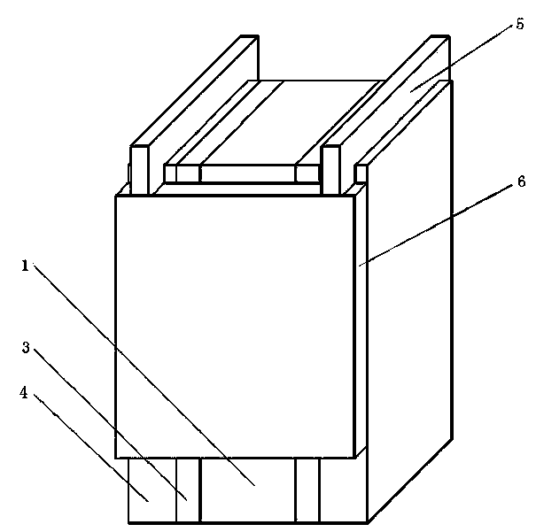
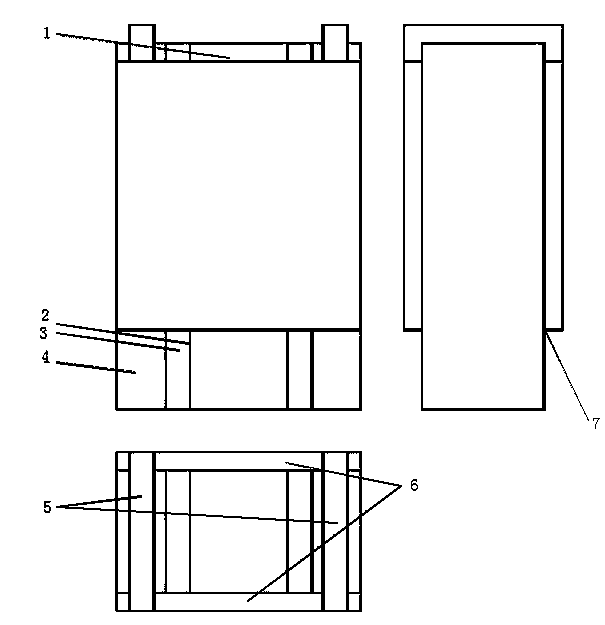
[0017] figure 1 , figure 2 Shown are a perspective view and a three-view view of the present invention respectively. The present invention is made up of micro burner 1, photoelectric conversion system and photovoltaic cell cooling system, and photoelectric conversion system is positioned at the both sides of micro burner 1, is made up of photovoltaic cell 3, and photovoltaic cell cooling system is positioned at the outside of photoelectric conversion system, consists of micro evaporator 4, Composed of steam pipeline 5, micro condenser 6 and liquid pipeline.

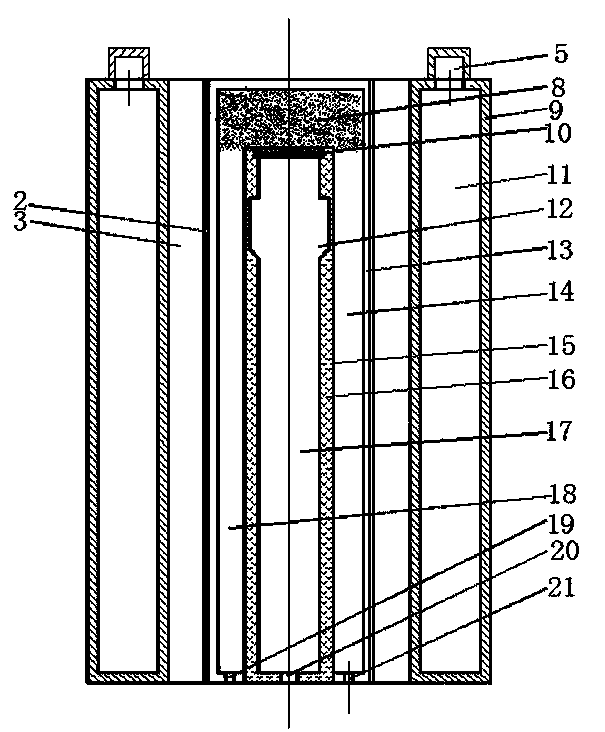
[0018] figure 2 It is a plane structure diagram of a micro burner 1, a glass heat insulating layer 2, a photovoltaic cell 3, and a micro evaporator 4. The micro burner 1 is made of a glass cover 13 sealingly wrapping a micro combustion chamber 17 . The micro-combustion chamber 17 is composed of a micro-combustion chamber shell 16 and a top plate porous medium panel 10 . The glass cover 13 bottom plates are flat wit...


PUM


Abstract

The invention discloses a micro thermal optoelectronic system cooled based on a loop heat pipe principle. The micro thermal optoelectronic system cooled based on the loop heat pipe principle is composed of a micro burner, a photoelectric converting system and a photocell cooling system. The photoelectric converting system is located on the two sides of the micro burner and is formed by photocells, and the photocell cooling system is located on the outer side of the photoelectric converting system and is formed by a micro evaporator, a steam pipeline, a micro condenser and liquid pipelines. According to the micro thermal optoelectronic system cooled based on the loop heat pipe principle, foamy copper is arranged between a porous medium top plate on the top of the micro combustion chamber and a glass shade top plate, a cavity structure is formed in the inner side of the vertical wall of the outer shell of the micro combustion chamber, a loop heat pipe system is adopted by the photocell cooling system, the evaporator is divided into a boiling chamber and a liquid suction chamber, a rhombus staggered columnar structure is designed inside the cavity of the condenser, a multiscale surface heat functional structure is adopted on the inner wall surface of the evaporator and the inner wall surface of the condenser, and the thermal performance of the system is improved. Compared with a normal heat pipe, the micro thermal optoelectronic system cooled based on the loop heat pipe principle structurally has the advantages that vapor pipelines and liquid pipelines are separated, and the evaporator and the condenser are integrated.

Description

technical field [0001] The invention belongs to the field of micro-power electromechanical systems, and in particular relates to a micro-thermal photoelectric system using a novel cooling device. Background technique [0002] In recent years, with the rapid development of high frequency, high speed, high integration and packaging technology of electronic components, new micro-thermal photoelectric new energy systems that are small in size, light in weight and high in energy density and meet the requirements of energy saving and emission reduction have been widely used. . The micro-thermo-photovoltaic system consists of a micro-burner, a photoelectric conversion system, and a photovoltaic cell cooling system. The combustion of hydrogen and oxygen in the micro-burner releases chemical energy, which makes the wall of the burner in a high temperature state. Through the selective coating material on the outer surface of the micro-burner, a spectrum of a certain wavelength is emi...

Claims


Application Information

Patent Timeline
IPC IPC(8): H02S40/42F23D14/66
CPCY02E10/50Y02E20/34
Inventor 吴鸽平虞永川马春花陆平王俊张敏
Owner JIANGSU UNIV
Learn More