A hydraulic impact rotary reverse circulation drilling device

A hydraulic impact and drilling device technology, which is applied to the driving device of rotary combined drilling, drilling equipment, earthwork drilling and production, etc., can solve the problems of small impact frequency adjustment range, low drilling efficiency, and low drilling efficiency. Achieve the effect of high utilization rate of impact energy, avoid repeated crushing, and solve construction problems

Active Publication Date: 2015-08-12
卓尔天成工程机械有限公司
View PDF10 Cites 0 Cited by
  • Summary
  • Abstract
  • Description
  • Claims
  • Application Information

AI Technical Summary

Problems solved by technology

[0003] When existing reverse circulation drill bits drill holes in hard rock formations, there is no need to consider the problem of circulating water leakage, and the drilling can proceed smoothly; while drilling in complex formations containing clay, quicksand, pebbles, gravels, boulders, etc., Due to the characteristics of uneven size, poor cementation, loose structure, frequent layer changes, and great disparity between hardness and softness, the fragments cannot be stably stressed during the drilling process, and are prone to rolling, resulting in multiple cutting surfaces, making The drilling efficiency is low, and accidents such as hole collapse, block dropping and drill sticking are prone to occur; due to the strong permeability of the broken ground, the flushing fluid is easily lost, resulting in interruption of circulating water, drilling cannot be carried out, and even water gushing and other accidents; the existing structure The medium circulating water channel is directly connected with the magma upward return center channel, which cannot form negative pressure in the drill bit area, resulting in difficulty in rock slag discharge and low construction efficiency
[0004] The reverse circulation faucet used in the drilling device is to suck the circulating water and rock slag out of the bottom surface from the bottom of the well through the central channel of the drilling tool and the faucet. At present, the faucet of the drilling rig has the following problems: the sealing device is not good, and there is a problem of air leakage and slurry leakage. Leading to interruption of circulating water; unreasonable structural design, unable to transmit impact energy and rotary energy to drilling tools at the same time, resulting in low drilling efficiency
[0005] The hydraulic impactor used in drilling is divided into the following two types according to the different power sources: one is to use the drilling flushing fluid as the power source, and use the valve plus return spring or valve sliding inertia to generate vibration to control the piston of the hydraulic impact cylinder. Vibration is generated, and the piston rod drives the impact hammer to impact the drill bit for impact rotary drilling operations. The impact frequency of this structure cannot be continuously adjusted, and the high-frequency vibration of the spring is easily damaged, and the slide valve is easily worn out by the high-abrasive drilling flushing fluid. Control function; the other is to use hydraulic oil as the power source. The drive system is isolated from the drilling flushing fluid. The impact frequency is generally determined by the hydraulic control reversing valve and the pressure of the hydraulic system. This structure has a complex impact frequency adjustment structure and high processing difficulty. , the impact frequency adjustment range is small, and only fixed frequency adjustment can be realized, but the drilling formation is ever-changing, and the impact force and frequency required for different formations are different. This hydraulic impact system has a small application range

Method used


Image

  • A hydraulic impact rotary reverse circulation drilling device
  • A hydraulic impact rotary reverse circulation drilling device
  • A hydraulic impact rotary reverse circulation drilling device

Examples


Embodiment Construction

[0014] The present invention will be further described below in conjunction with the accompanying drawings.

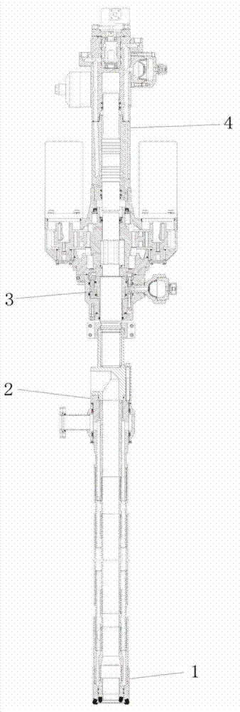
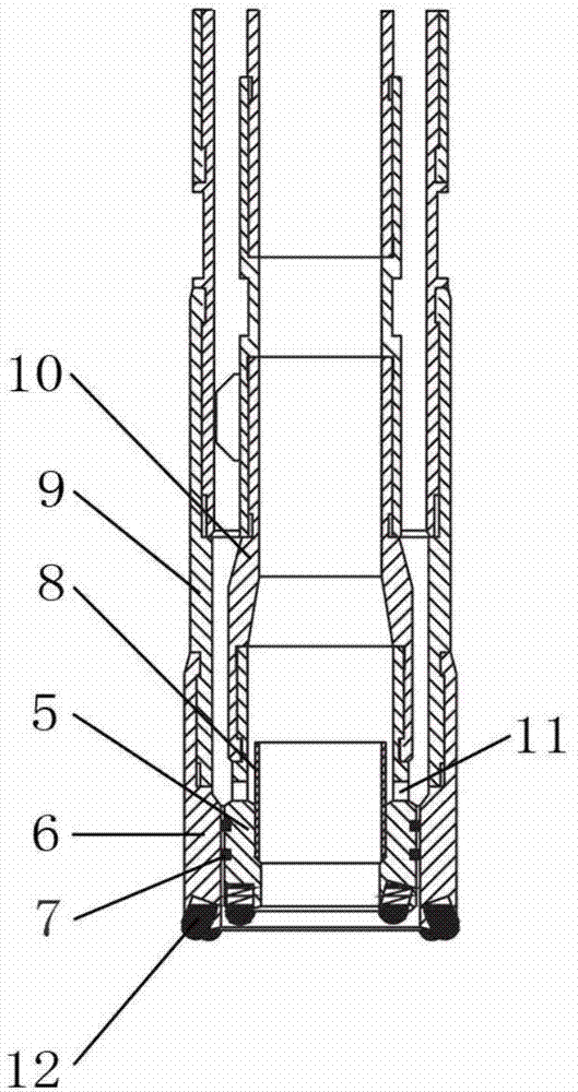
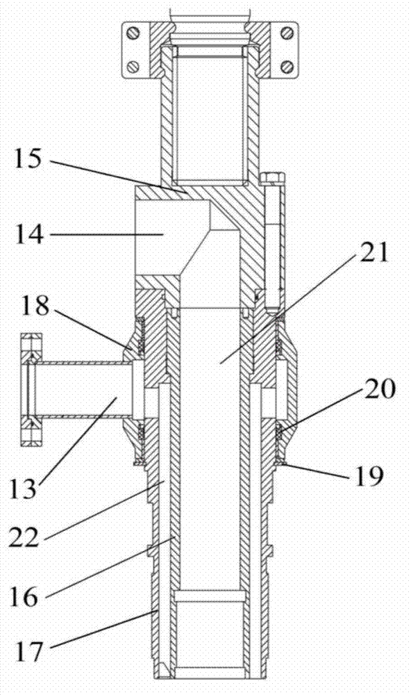
[0015] In the figure: 1-reverse circulation drill bit, 2-reverse circulation faucet, 3-power head, 4-hydraulic impactor, 5-drill bit body, 6-casing boot, 7-sealing ring, 8-guiding sleeve, 9 -transition joint, 10-flow diversion joint, 11-through hole, 12-ball finger alloy, 13-water inlet, 14-slag discharge port, 15-impact swivel joint, 16-drill pipe joint, 17-casing joint, 18-water jacket, 19-circlip, 20-sealing ring, 21-magma upward return center channel, 22-high pressure circulating water channel, 23-front shell, 24-rear shell, 25-impact piston, 26-storage Energy device, 27-oil pipe joint, 28-reversing valve core, 29-reversing valve sleeve, 30-hydraulic motor, 31-mounting seat.

[0016] Embodiment: The reverse circulation drill bit 1 is connected to the lower end of the reverse circulation faucet 2, the upper end of the reverse circulation faucet 2 is connected to th...


PUM


Abstract

The invention belongs to the field of drilling equipment and particularly relates to a hydraulic percussion rotary reverse circulation drilling device. The hydraulic percussion rotary reverse circulation drilling device comprises a reverse circulation drill bit, a reverse circulation faucet, a power head and a hydro-percussive hammer and is characterized in that the lower end of a drill bit body in the reverse circulation drill bit and the lower end of a casing shoe are sealed through a seal ring, a flow guide sleeve is fixedly connected onto the inside of the lower end of the drill bit body, the upper surface of the flow guide sleeve is higher than a through hole, the water inlet in the reverse circulation faucet is formed in one side of a water jacket and penetrates a sleeve joint to be communicated with a high-pressure circulating water channel, the water jacket is sleeved outside the sleeve joint and is fixed through a snap spring, a seal ring is arranged between the sleeve joint and the water jacket, a deslagging opening is formed in one side of a percussion rotary joint and is communicated with a magma reverse central channel, a hydraulic motor of the hydro-percussive hammer is fixed on a mounting base and is connected with a reversing valve core, the mounting base is fixed on a rear shell and the upper end of a reversing valve sleeve, and the reversing valve sleeve is arranged inside the rear shell and sleeved outside the reversing valve core. The hydraulic percussion rotary reverse circulation drilling device can be used for performing efficient construction in water-free gravel-cobble stratums.

Description

technical field [0001] The invention belongs to the field of drilling equipment, in particular to a reverse circulation drilling device. Background technique [0002] At present, the most efficient drilling method for breaking complex formations is the combination of impact rotary and reverse circulation drilling technology. The reverse circulation drill bit, the reverse circulation drill bit impacts the rock with high frequency to break the rock, and the high-pressure circulating water enters the bottom of the reverse circulation drill bit through the reverse circulation drill bit, and the high-pressure circulating water entrains the rock slag and returns to the center from the magma by the reverse circulation slag discharge method channel discharge. The reverse circulation drill bit, the reverse circulation faucet and the hydraulic impactor are the indispensable components in the impact rotary reverse circulation drilling device. [0003] When existing reverse circulatio...

Claims


Application Information

Patent Timeline
Patent Type & Authority Patents(China)
IPC IPC(8): E21B6/00
Inventor 宗文光
Owner 卓尔天成工程机械有限公司
Why Eureka
Try Eureka