
nrz to prz code conversion fiber grating design method and device

A fiber grating and code pattern conversion technology, applied in the field of optical communication, can solve the problems of recovery time effect, code pattern effect, power loss increase, etc. Effect

Inactive Publication Date: 2015-10-07
FOSHAN UNIVERSITY +1
View PDF4 Cites 1 Cited by
  • Summary
  • Abstract
  • Description
  • Claims
  • Application Information

AI Technical Summary

Problems solved by technology

Among them, SOALOM has a large volume, is not easy to integrate, and is very sensitive to polarization. It can work well at 10Gb / s and 20Gb / s rates. For higher rates, there will be serious pattern effects.
On the basis of SOALOM, the SOA series filter scheme is further simplified, which greatly simplifies the experimental equipment, but it will still be affected by the SOA carrier recovery time
Fiber delay interferometer DI is a passive device, has nothing to do with polarization, and there is no SOA pattern effect and ASE noise, etc., but DI needs a temperature control device, which is difficult to manufacture in high-speed applications
The optical bandpass filter detuning filtering solution has a simple structure and can work passively. It is suitable for high-speed code conversion, but the power loss caused by the bandpass filter is large, the Q factor is low, and the conversion effect is not ideal. In particular, it needs The DC component is suppressed by increasing the detuning amount of the filter. In this case, the power loss also increases accordingly, which makes the impact of noise very obvious, so the quality of the converted PRZ signal will drop sharply, which is not conducive to the next step of clock recovery. realization of

Method used


Image

  • nrz to prz code conversion fiber grating design method and device
  • nrz to prz code conversion fiber grating design method and device
  • nrz to prz code conversion fiber grating design method and device

Examples


Embodiment 1

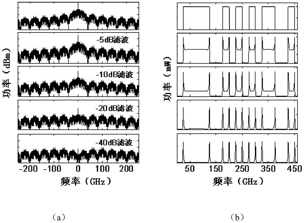
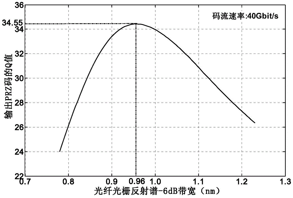
[0049] The embodiment of the present invention provides a device for converting NRZ to PRZ codes with a code rate of 40Gbit / s as the optimal operating point and a dynamic application range of 17Gbit / s to 70Gbit / s, so as to convert the NRZ signal to be converted into a PRZ signal , the specific principle is as figure 1 As shown, the NRZ signal enters the fiber grating 2 from the input terminal 1, and the PRZ signal is output from the output terminal 3. The code conversion device is essentially a specially designed fiber grating, and its transmission spectrum is optimized according to the characteristics of the NRZ spectrum structure and the filtering requirements of NRZ to PRZ code conversion. Perform notch filtering to greatly attenuate the low-frequency components near the carrier, and pass the high-frequency components without attenuation, so as to realize the conversion from NRZ to PRZ code, and obtain the PRZ code stream at the transmission end of the fiber grating. figur...

Embodiment 2

[0081] The embodiment of the present invention provides a device for converting NRZ to PRZ codes with 60Gbit / s code stream rate as the optimal working point and 26Gbit / s to 102Gbit / s as the dynamic applicable range, so as to convert the NRZ code stream to be converted into PRZ stream. The code conversion device is a fiber grating, and its transmission spectrum is used for notch filtering of the NRZ spectrum, attenuating the DC and low frequency components, extracting the high frequency components containing jump information, and forming pulses at the jumps of the NRZ code stream signal to get the PRZ code stream output.

[0082] The steps adopted in this embodiment are the same as those in Embodiment 1. According to the steps described in Embodiment 1, the -6dB bandwidth of the fiber grating reflection spectrum in this embodiment takes a value between 0.9nm-1.5nm, and simulates the notch filter process to obtain The variation of the Q value of the PRZ code stream with the -6d...

Embodiment 3

[0086] Utilize the NRZ described in embodiment 1 or embodiment 2 to PRZ pattern conversion fiber grating design method can obtain such as figure 1 The shown NRZ to PRZ all-optical code conversion device. It is used to convert the NRZ signal to be converted into the corresponding PRZ signal within the code rate range of plus or minus one-half of the optimal operating point, including a fiber grating with a specific notch-type spectral response. The fiber grating includes an input port for NRZ signal input and an output port for PRZ signal output. The transmission spectrum of the fiber grating is designed to attenuate the direct current and low frequency components within a certain range near the fundamental frequency in the NRZ spectrum to an extremely low level while passing most frequency components, and its function is equivalent to a notch filter.

[0087] The notch width and notch center position of the notch filter formed by the spectral response of the fiber grating ar...


PUM


Abstract

The invention discloses a non return to zero (NRZ)-to-pseudo return to zero (PRZ) code pattern conversion optical fiber grating design method and a non return to zero (NRZ)-to-pseudo return to zero (PRZ) code pattern conversion device. The non return to zero (NRZ)-to-pseudo return to zero (PRZ) code pattern conversion optical fiber grating design method comprises the following steps that: the reflectivity and transmissivity of a fiber bragg grating are described through using a super Gaussian function; two decibel values of a reflection spectrum and the difference of bandwidths of the decibel values are selected; the bandwidth value of one decibel value of the reflection spectrum is set so as to solve the super Gaussian function, such that a transmissivity function can be obtained; the frequency spectrum of inputted non return to zero (NRZ) code streams is multiplied by the transmissivity function such that the frequency spectrum of code streams after filtering can be obtained, and then, inverse Fourier transform is performed on the frequency spectrum of the code streams so as to obtain code steam waveform of time domain after filtering; Q values of the code streams are calculated; different bandwidth values of one decibel value are selected so as to obtain a plurality Q values; a maximum Q value and an optimal bandwidth value are found out, and a corresponding transmissivity function is the transmission spectrum of the fiber bragg grating; a refractive index modulation function and a local chirp function are obtained through adopting methods comprising a discrete inversion layer stripping method. The non return to zero (NRZ)-to-pseudo return to zero (PRZ) code pattern conversion optical fiber grating design method of the invention has the advantages of larger pass-band, higher Q value, optimally-designable wave notching and filtering characteristics, optimal filtering effect and high-quality code pattern conversion.

Description

technical field [0001] The present invention relates to the technical field of optical communication, in particular to an all-optical code conversion optical grating design method and a conversion device thereof from non-return-to-zero code (NRZ) to pseudo-return-to-zero code (PRZ). Background technique [0002] All-optical clock recovery is an important technology for future high-speed and large-capacity optical communication systems. As for the return-to-zero (RZ) code pattern, because the clock component in its frequency spectrum is very strong, it is very convenient to directly extract the clock. However, for the non-return-to-zero (NRZ) code pattern, the clock component in its frequency spectrum is very weak, and it is impossible to directly extract the clock component, and preprocessing is required first. Since the pseudo-return-to-zero (PRZ) pattern contains a strong clock component in its spectrum, and the conversion from NRZ pattern to PRZ pattern is much simpler t...

Claims


Application Information

Patent Timeline
Patent Type & Authority Patents(China)
IPC IPC(8): G02B27/00G02B6/02
Inventor 曹辉舒学文齐佳楠左军樊婷
Owner FOSHAN UNIVERSITY
Learn More