User-defined bus and achievement method thereof

A self-defined bus and bus technology, applied in the direction of instruments, electrical digital data processing, etc., can solve the problems of complex protocols, decreased communication effectiveness, complex high-speed buses, etc., to achieve simple communication protocols, save data transmission and processing time, and satisfy The effect of real-time transmission

Active Publication Date: 2014-03-05
XBO MEDICAL SYST
View PDF3 Cites 6 Cited by
  • Summary
  • Abstract
  • Description
  • Claims
  • Application Information

AI Technical Summary

Problems solved by technology

However, there are two unavoidable problems in the use of universal high-speed bus, namely the protocol problem and the problem of real-time data transmission.
Not only does it require the support of many dedicated chips on the hardware, but it also requires complex protocol support at the level of operating system application software.
[0003] Universal high-speed bus is suitable for general application environments, but under specific functional requirements, universal high-speed bus is complicated and cumbersome
There are the following problems when using the general high-speed bus to transmit sporadic data: (1) Sporadic data cannot be packaged into large blocks of data for transmission, and the general high-speed bus is occupied for a long time, which will cause sporadic data to be blocked
(2) Detection or control signals are queued in the data queue and wait for sequential transmission, which may easily cause time delays
(3) After sporadic data is encapsulated by the protocol, a lot of extra data will be added, which will reduce the effectiveness of communication
(4) The design process of hardware and software is complicated, and the existing data acquisition equipment uses a single high-speed bus for data transmission, and its software design is relatively complicated, lacking the flexibility of equipment control
(5) Universal high-speed bus cannot meet the requirements of real-time data transmission

Method used


Image

  • User-defined bus and achievement method thereof
  • User-defined bus and achievement method thereof
  • User-defined bus and achievement method thereof

Examples


Embodiment

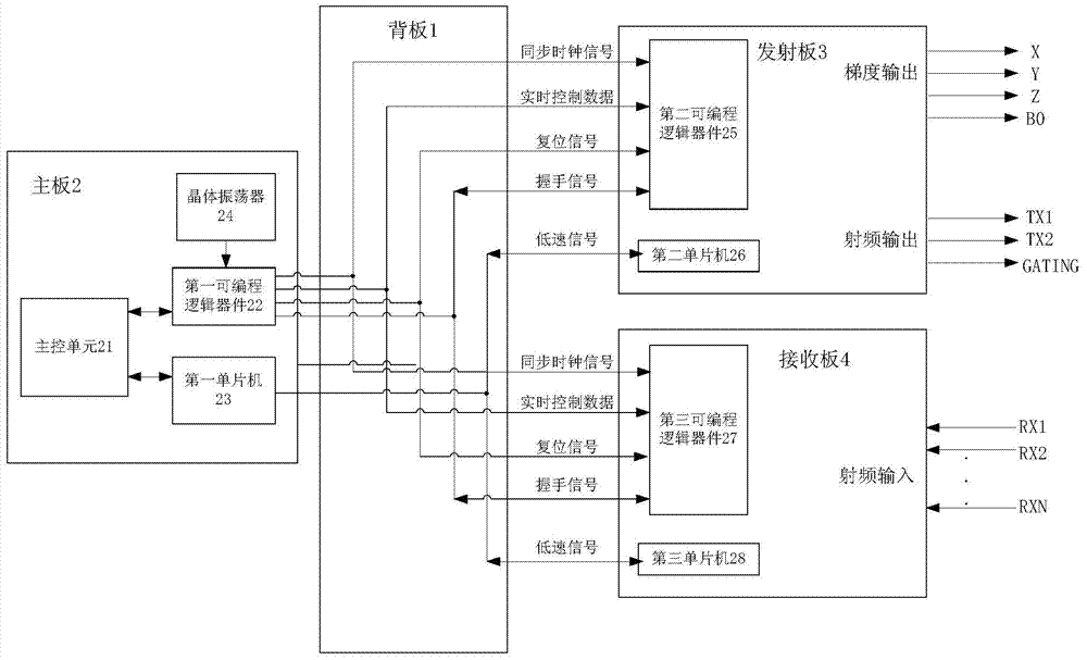
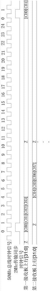
[0037] Example: such as image 3 As shown, the crystal oscillator 24 generates a clock signal and transmits it to the first programmable logic device 22, and the first programmable logic device 22 performs shaping, frequency division and other processing on the clock signal to generate a 50MHz bus clock signal line and A 2MHz transmit synchronous clock signal. Each 2MHz transmission synchronous clock is used to mark the start of a transmission cycle, and there are 25 50MHz bus clocks within each 2MHz transmission synchronous clock. The first transmission cycle begins, and the first receiving board 4 of the uplink receiving bus defines the received 4-way magnetic resonance signals as 4*32-bit data for transmission, and transmits a 32-bit data in each 50MHz bus clock; the second During the bus clock cycle when one receiving board 4 transmits data through the uplink receiving bus, the other receiving boards 4 are in a high-impedance state. Within the bus clock period after the ...


PUM


Abstract

The invention relates to a user-defined bus and an achievement method thereof. The method includes the steps that the bus comprising a back panel, a main panel, a transmitting panel and a plurality of receiving panels is set, a main control unit, a first programmable logic component, a first single chip microcomputer and a crystal oscillator are arranged in the main panel, a second programmable logic component and a second single chip microcomputer are arranged in the transmitting panel, a third programmable logic component and a third single chip microcomputer are arranged in each receiving plate, high-speed buses are arranged between the first programmable logic component and the second programmable logic component and between the first programmable logic component and the third programmable logic components and are used for transmitting real-time control data, reset signals, handshaking signals, reserved signals, bus clock signals and synchronous clock signals, low-speed buses are arranged between the first single chip microcomputer, and the second single chip microcomputer and between the first single chip microcomputer and the third single chip microcomputers and are used for transmitting initial signals or random detection signals. The user-defined bus can be widely used in magnetic resonance spectrometer systems.

Description

technical field [0001] The present invention relates to a bus and its implementation method, in particular to a self-defined bus for a magnetic resonance spectrometer system and its implementation method Background technique [0002] At present, acquisition cards, spectrum analyzers, and some large-scale communication and data processing equipment mostly use general-purpose high-speed buses for data transmission. The general-purpose high-speed buses can use PCI (Peripheral Component Interconnect, peripheral component interconnection standard) buses, PCIe (PCI Express, A new generation of bus interface) bus or network. The universal high-speed bus has the advantages of high speed and compatibility with other devices. For example, the current highest version of PCIe 16X2.0 can reach 10Gb / s, and network communication can also reach 1Gb / s. However, there are two unavoidable problems in using the universal high-speed bus, namely the protocol problem and the real-time data trans...

Claims


Application Information

Patent Timeline
Patent Type & Authority Applications(China)
IPC IPC(8): G06F13/40
Inventor 侯晓萍刘景顺迈特·康明斯王义槐刘培植连建宇
Owner XBO MEDICAL SYST
Why Eureka
Try Eureka