High-precision tunnel cross section detection method and device based on double laser bands

A detection device and detection method technology, applied in the direction of measuring devices, optical devices, instruments, etc., can solve the problems of difficulty in improving the real-time processing speed of each frame of high-speed images, the inability to achieve high-speed and high-precision measurement, and the low accuracy of section detection. Achieve the effect of high-precision tunnel section detection method, compact structure, and improved detection accuracy

Active Publication Date: 2014-03-12
BEIJING MASS TRANSIT RAILWAY OPERATION CORPORATION LIMITED +1
View PDF5 Cites 18 Cited by
  • Summary
  • Abstract
  • Description
  • Claims
  • Application Information

AI Technical Summary

Problems solved by technology

[0003] Tunnel section detection technologies mainly include laser scanning measurement method and laser triangulation method. In the actual detection process of the existing technology, the main disadvantages are: ①Laser scanning measurement is point-by-point scanning, and the distance is calculated by using the time of laser emission and reception. The rotation is controlled by the motor. Affected by the scanning frequency, angular resolution, detection speed, etc., the light spot scans in a spiral shape, and the detection accuracy of the cross-section is low. Especially for objects with small cross-sections, there are often missed detections.
②Synchronous detection of high-speed cameras by laser triangulation method. Under the premise of satisfying the image resolution, the image acquisition frequency shall not exceed 500Hz. , there are still missed detections
At present, the development of high-resolution real-time image processing hardware for high-speed cameras is relatively difficult, and is limited by image processing algorithms. It is difficult to improve the real-time processing speed of each frame of high-speed images, so bottlenecks are encountered in hardware and algorithm speed-up.
At the same time, due to the increase of tunnel lines and the continuous improvement of detection speed requirements, the existing detection technology is still unable to achieve high-speed and high-precision measurement

Method used


Image

  • High-precision tunnel cross section detection method and device based on double laser bands
  • High-precision tunnel cross section detection method and device based on double laser bands
  • High-precision tunnel cross section detection method and device based on double laser bands

Examples


Embodiment 1

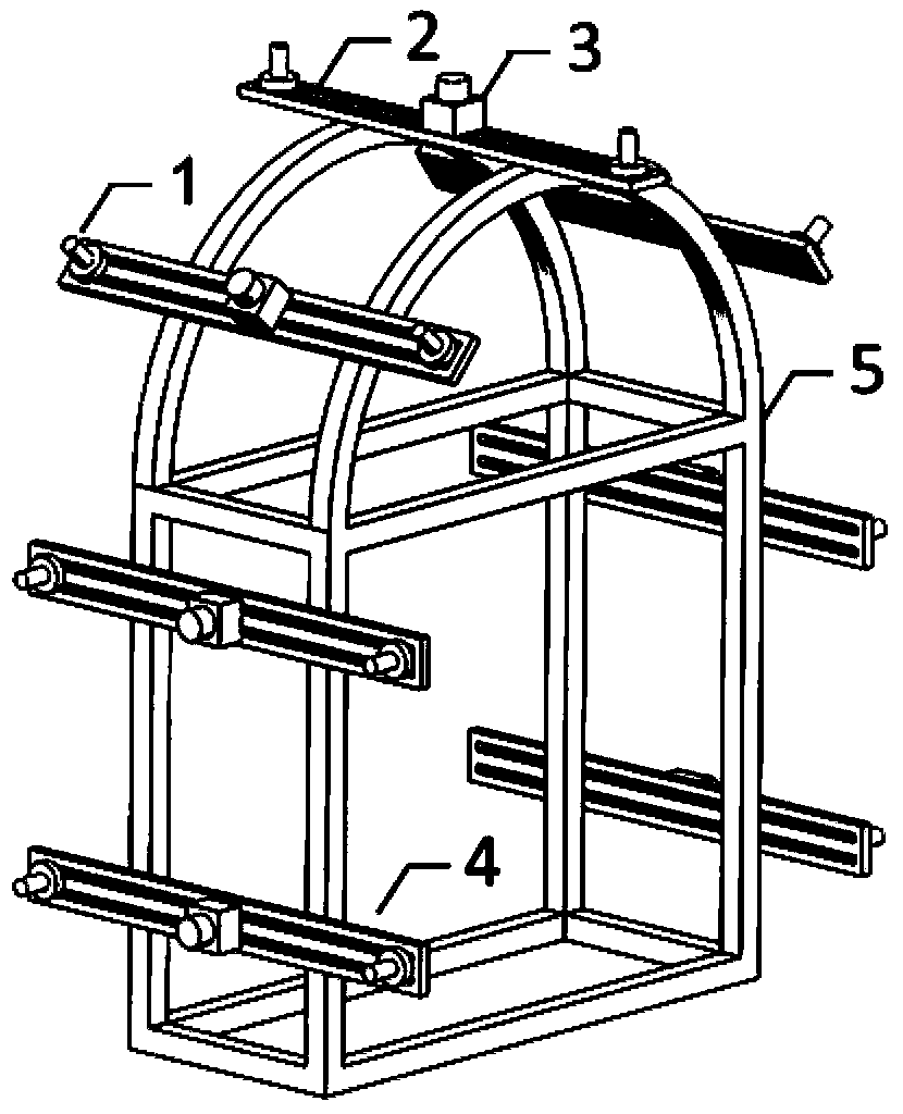
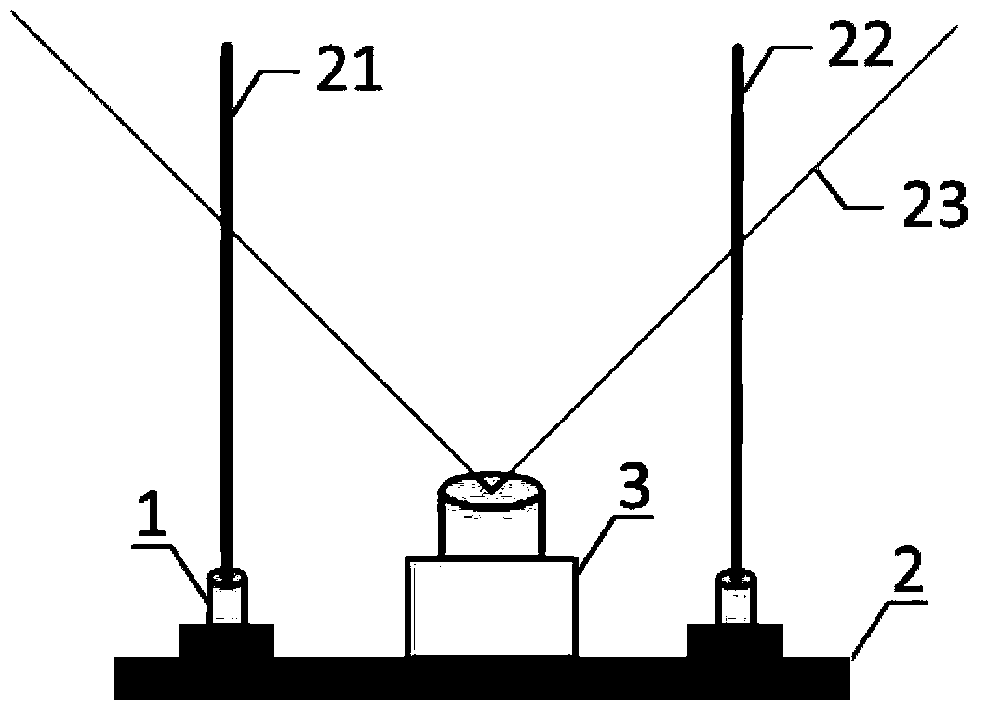
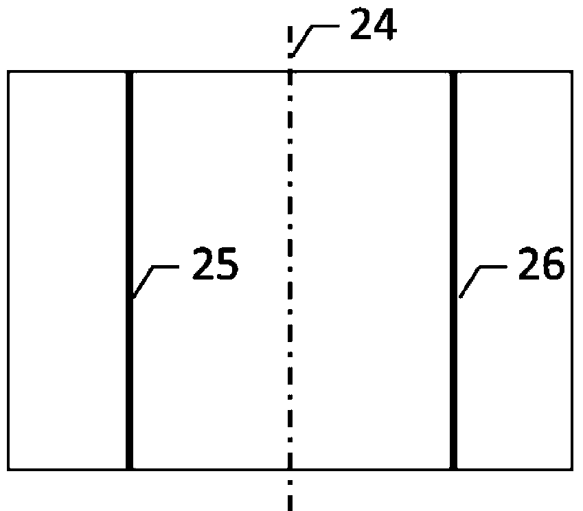
[0019] The present invention is mainly equipped on a flat-panel detection vehicle that can move on the railway, and each two line lasers 1 and a high-speed industrial camera 3 are installed on the base 2 of the laser and the high-speed camera to form a local double-light belt detection device 4, Several partial double-light strip detection devices are arranged in parallel in the vertical direction to form an overall double-light strip detection system. During detection, adjust the position of the overall main body adjustment bracket 5, so that the spliced ​​two line lasers 21 and 22 vertically scan into the high-speed industrial camera image acquisition area 23 on the tunnel surface, and form the first laser band 25 and the second laser band on the tunnel surface. Two laser bands 26 . At this time, in the tunnel environment, the parameters of the high-speed industrial camera 3 and the lens are adjusted so that the system can normally collect the image data of the two laser ban...

Embodiment 2

[0021] The image processing and model calculation of the dual-light zone tunnel section detection system are completed on the high-speed image acquisition card with FPGA as the processing core. Each high-speed industrial camera 3 corresponds to an image acquisition and processing card, such as image 3 As shown, the multi-channel acquisition card is connected with the industrial computer through the PCI bus. The acquisition card performs image filtering, threshold segmentation, and light band center pixel extraction algorithms on the image in the window by means of hardware circuits. These algorithms are implemented by hardware language and loaded into the FPGA processing chip for high-speed parallel processing. During data transmission, each high-speed camera transmits detection data to the industrial computer synchronously in real time through the image acquisition card, including the image coordinates of the central pixel of the double light strip. During the calibration p...


PUM


Abstract

The invention relates to the technical field of measuring instruments, in particular to a high-precision tunnel cross section detection method and a high-precision tunnel cross section detection device based on double laser bands. The device is used for measuring the tunnel cross section dimension and the limit detection, and is mainly applicable to the high-precision and high-density cross section detection of railway tunnels. A plurality of linear lasers are utilized for taking photos on the surface of the tunnels, two complete tunnel cross section outline light bands are formed, a high-speed visual system is used for collecting light band images, the images are subjected to high-speed parallel processing for extracting light band positions, the actual tunnel cross section coordinates are calculated through a system calibration technology, and the high-speed real-time tunnel cross section detection function is realized. The method and the device provided by the invention have the advantages that a camera collection region is reasonably utilized, so the cross section detection precision and the density are exponentially improved, the structure is compact, the integrality is high, and the method and the device can also be used in high-speed detection of tunnel local sensitive regions.

Description

technical field [0001] The invention relates to a high-speed real-time tunnel section limit detection system, in particular to a tunnel section high-precision detection method using dual-light band laser photography and high-speed visual detection technology. Background technique [0002] The periodic section measurement and infrastructure limit detection of railway tunnels are of great significance to the safe operation of trains. In recent years, domestic rail transit is in a period of rapid development, especially the rapid development of urban subways, and the demand for tunnel section detection technology is increasing. Due to changes in geological structure, tunnel construction maintenance, long-term impact of trains, etc., local deformation of the cave body, intrusion of infrastructure, and falling off of auxiliary equipment frequently occur. Therefore, high-precision measurement of tunnel sections can find problems and guide maintenance to ensure Driving safety. ...

Claims


Application Information

Patent Timeline
Patent Type & Authority Applications(China)
IPC IPC(8): G01B11/25
Inventor 刘建余祖俊王思民王耀东朱力强刘峙松张岚徐田坤
Owner BEIJING MASS TRANSIT RAILWAY OPERATION CORPORATION LIMITED
Why Eureka
Try Eureka