Strengthening and regenerating system and method for carbon dioxide capturing solution

A carbon dioxide regeneration system technology, applied in chemical instruments and methods, separation methods, inorganic chemistry, etc., can solve problems such as increasing technology application costs, and achieve the effects of reducing degradation loss, regeneration temperature, and carbon dioxide load

Active Publication Date: 2014-03-19
HUANENG CLEAN ENERGY RES INST
View PDF2 Cites 23 Cited by
  • Summary
  • Abstract
  • Description
  • Claims
  • Application Information

AI Technical Summary

Problems solved by technology

The cost caused by the degradation of the absorbent in the conventional monoethanolamine-based capture system accounts for more than 5% of the total system cost and more than 10% of the system's operating cost. The disposal of by-products related to safety and environmental protection It will also increase the cost of technology application

Method used


Image

  • Strengthening and regenerating system and method for carbon dioxide capturing solution
  • Strengthening and regenerating system and method for carbon dioxide capturing solution

Examples


Embodiment 1

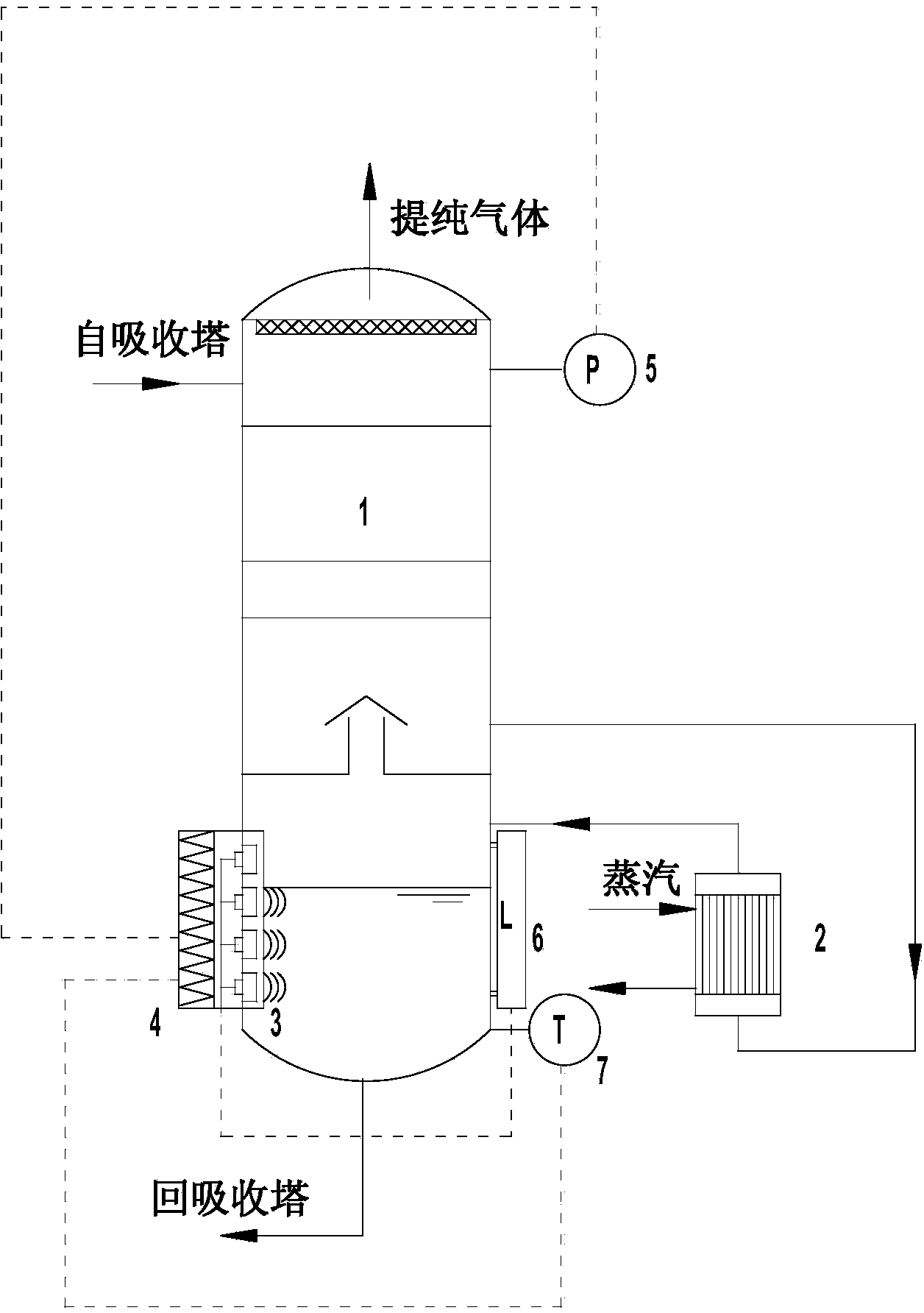
[0025] As attached figure 1 The regeneration tower 1 is connected to the absorption tower. The absorption solution reacts with carbon dioxide in the absorption tower to form a rich liquid that leaves the absorption tower. It enters the regeneration tower 1 from the top of the regeneration tower 1 and flows to the lower part, and the solution enters the vertical connected to the lower side of the regeneration tower 1 Type or horizontal thermosiphon reboiler 2, the reboiler 2 is provided by external steam as a heat source, the absorbing solution absorbs heat and returns to the regeneration tower 1 to maintain the temperature and pressure in the regeneration tower 1.

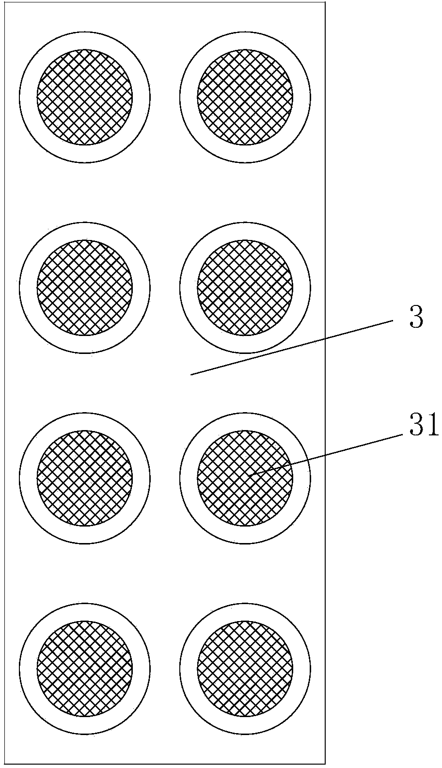
[0026] Two ultrasonic generator panels 3 are parallel and equal in height on both sides of the bottom side wall of the regeneration tower 1, such as figure 2 As shown, the inside of the ultrasonic generator panel 3 is composed of multiple sets of ultrasonic vibrators located at different heights, the vibrators output ...

Embodiment 2

[0028] The structure of regeneration tower 1, reboiler 2 is the same as that of example 1. The ultrasonic generator panel 3 is placed flat at the bottom of regeneration tower 1, and ultrasonic waves are output from the bottom to the solution. The solution flowing from reboiler 2 into regeneration tower 1 is completely immersed in ultrasonic generation. According to the liquid level information at the bottom of the regeneration tower fed back by the liquid level sensor 6, after the liquid level reaches a certain value, the vibrator of the ultrasonic generator panel 3 is turned on and the number of working vibrators is adjusted according to the change of the liquid level. The ultrasonic controller 4 modulates the output frequency and power of the vibrator on the ultrasonic generator panel 3 according to the feedback values ​​of the pressure sensor 5 and the temperature sensor 7. When the modulation frequency and power range are lower than the limit, the vibrators on the ultrasonic ...


PUM


Abstract

A strengthening and regenerating system for a carbon dioxide capturing solution comprises a regeneration tower, a reboiler, a supersonic generator panel, a supersonic controller, a pressure sensor, a liquid position sensor, and a temperature sensor; rich liquor from an absorption tower enters the regeneration tower from the top part of the regeneration tower, then flows to the bottom part of the regeneration tower, enters the reboiler, absorbs the thermal energy there, and then is returned to the regeneration tower; when the solution submerges the supersonic generator panel, according to the liquid position information obtained by the liquid position sensor, a vibrator in the supersonic generator panel under the liquid position is started to work, then the carbon dioxide in the liquid phase is promoted to evaporate from the liquid phase through a supersonic cavitation effect, then the carbon dioxide rises to the top part of the regeneration tower and forms a pressure; and according to the pressure value measured by the pressure sensor and the temperature value measured by the temperature sensor, the supersonic controller adjusts the output frequency and power of the vibrator in the supersonic generator panel. The system can accelerate the evaporation speed of the carbon dioxide in the solution, reduces the desorption temperature, reduces the external steam consumption, improves the absorption rate of carbon dioxide and the regeneration degree of the solution, and reduces the energy consumption of each unit of carbon dioxide.

Description

Technical field [0001] The invention belongs to the technical field of flue gas carbon dioxide capture, and particularly relates to a carbon dioxide capture solution enhanced regeneration system and method. Background technique [0002] The large-scale emission of greenhouse gases caused by industrial production is an important reason for the frequent occurrence of extreme weather. Therefore, the reduction of greenhouse gas emissions represented by carbon dioxide has increasingly attracted the attention of the international community. The burning of fossil fuels in power plants is the main source of industrial carbon dioxide emissions. In my country, carbon dioxide emissions from power plants account for about half of the total emissions. Carbon dioxide capture technology for gas is an essential component. [0003] The existing carbon dioxide capture technologies are mainly divided into pre-combustion, post-combustion, oxy-fuel combustion and compression cooling separation methods....

Claims


Application Information

Patent Timeline
Patent Type & Authority Applications(China)
IPC IPC(8): B01D53/18C01B31/20C01B32/50
CPCY02A50/20Y02P20/151
Inventor 王金意许世森郜时旺郭东方刘练波牛红伟王晓龙
Owner HUANENG CLEAN ENERGY RES INST
Why Eureka
Try Eureka