

Periodic signal enhancement detection device and method
A periodic signal and detection device technology, applied in measurement devices, measurement of ultrasonic/sonic/infrasonic waves, instruments, etc., can solve problems such as the universal detection limitation of actual periodic signals, and the difficulty of automatic and intelligent adjustment of detection circuit system parameters. , to achieve the effect of easy to achieve mass production, easy to understand, and good detection effect
- Summary
- Abstract
- Description
- Claims
- Application Information
AI Technical Summary
Problems solved by technology
Method used
Image

Examples
Embodiment 1
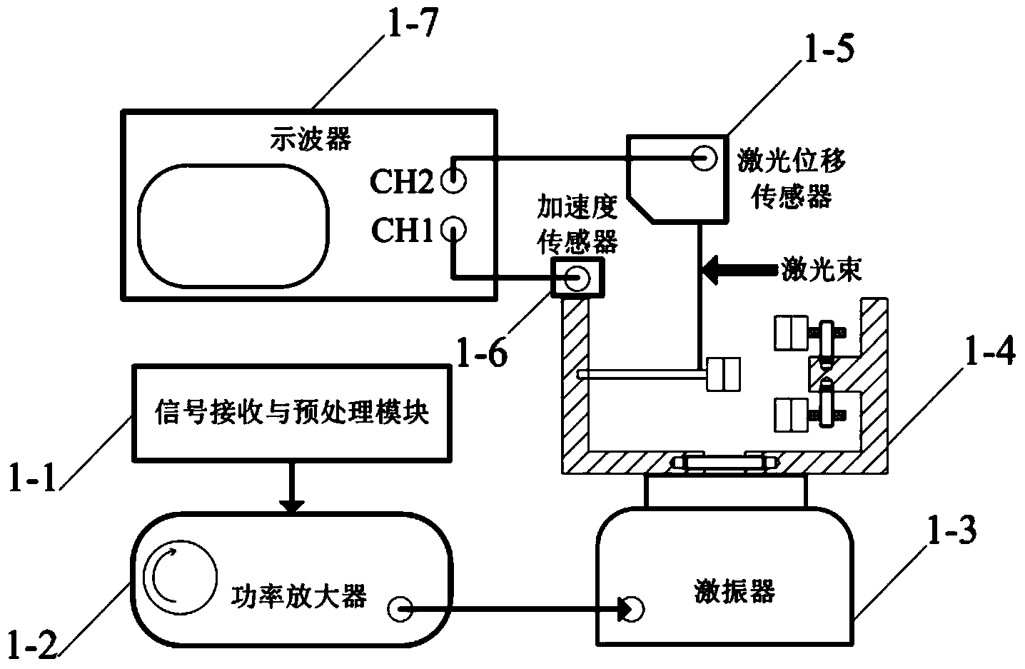
[0032] According to the above invention content and appended figure 1 A structural diagram of a periodic signal enhancement detection device, which specifically includes a receiving and preprocessing module 1-1, a power amplifier 1-2, an exciter 1-3, a three-stable cantilever beam physical device 1-4, and a laser displacement sensor 1-5, acceleration sensor 1-6, oscilloscope 1-7. The output interface of the signal receiving and preprocessing module 1-1 is connected to the input interface of the power amplifier 1-2; the output interface of the power amplifier 1-2 is connected to the input interface of the exciter 1-3; the three-stabilized cantilever beam physical device 1 -4 is bolted to the workbench of the shaker 1-3; the laser displacement sensor 1-5 is installed on a suitable bracket to ensure that the laser beam is aimed at the cantilever in the tri-stable cantilever physics setup 1-4 to vibrate freely terminal; the acceleration sensor 1-6 is connected to the three-stable...
Embodiment 2
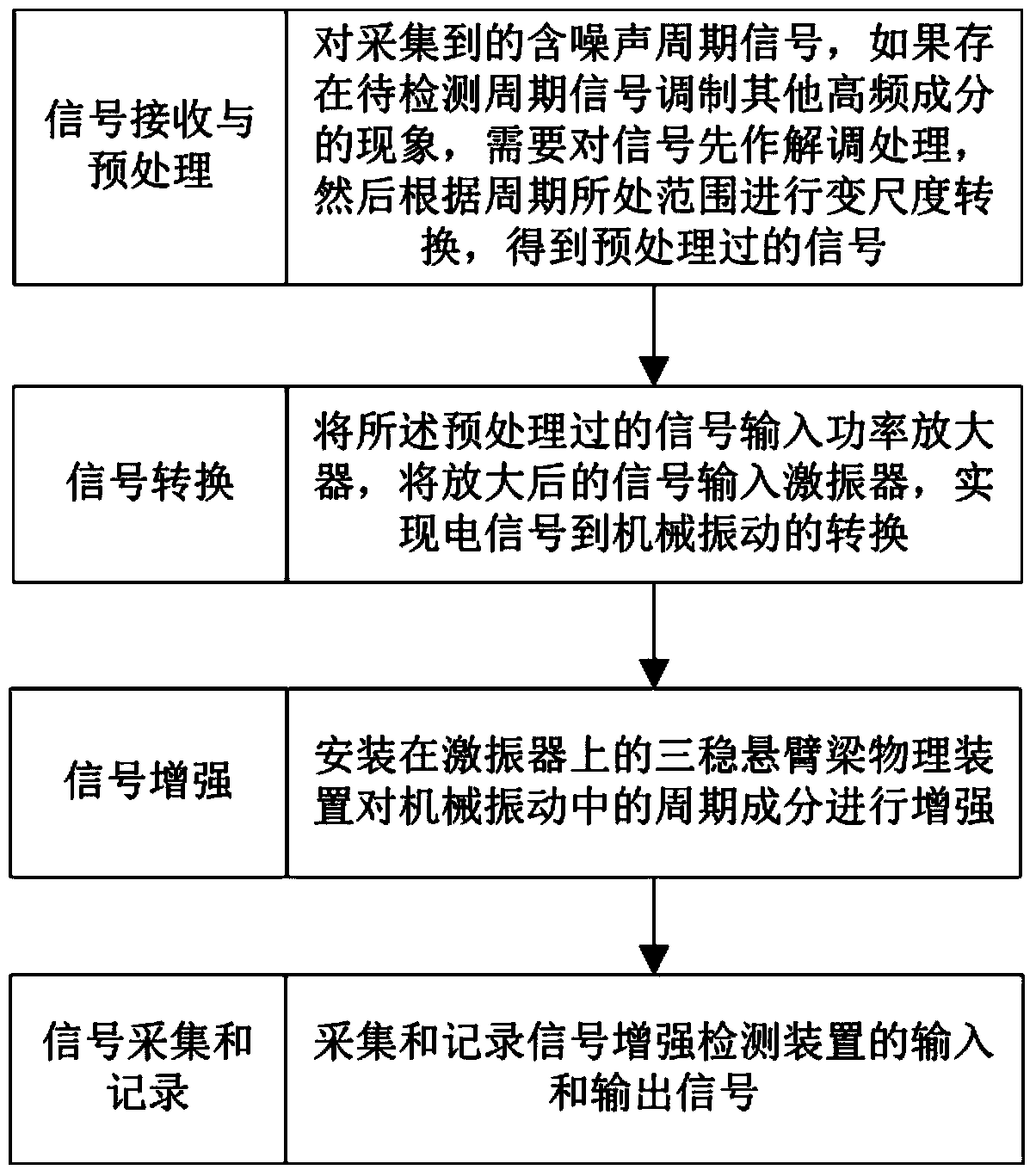
[0036] According to attached image 3 A flowchart of a periodic signal enhancement detection technology, the specific execution process of the periodic signal enhancement detection method specifically includes the following steps.
[0037] Step 1. For the collected periodic signal containing noise, if there is a phenomenon that the periodic signal to be detected modulates other high-frequency components, it is necessary to demodulate the signal first, and then perform scale conversion according to the range of the period to obtain the preprocessed signal of;
[0038] Step 2, inputting the preprocessed signal into a power amplifier, and inputting the amplified signal into a vibrator to realize the conversion from an electrical signal to a mechanical vibration;
[0039] Step 3, the three-stable cantilever beam physical device installed on the exciter strengthens the periodic component in the mechanical vibration;
[0040] Step 4, collecting and recording the input and output s...
Embodiment 3
[0046] In order to understand the technical solution of the present invention and its effect more clearly, a specific embodiment will be described in detail below. according to figure 1 An experimental platform is built, and the signal used for the test of the embodiment is a rotating machinery fault simulation signal. The signal is composed of periodic unilateral attenuation pulses and additive Gaussian white noise. The frequency of fault pulses is 8.8 Hz.
[0047] First, according to image 3 Step 1: Carry out envelope demodulation on the fault signal by Hilbert transform method. Since the fault frequency of 8.8Hz is within the effective working range of the signal enhancement detection device, X=1 is selected, that is, the signal is played at the original speed.
[0048] Subsequently, according to image 3 Step 2: Input the demodulated fault signal into the power amplifier, and the output signal of the power amplifier drives the electromagnetic exciter to cause the vibra...
PUM
 Abstract
Description
Claims
Application Information