Uninterrupted power supply method and uninterrupted power source system
A power supply method and power system technology, applied in the direction of emergency power supply arrangements, electrical components, circuit devices, etc., can solve the problems of long charging time, pollution, short service life of batteries, etc., and achieve the effect of huge application potential and economic benefits
- Summary
- Abstract
- Description
- Claims
- Application Information
AI Technical Summary
Problems solved by technology
Method used
Image

Examples
Embodiment 1
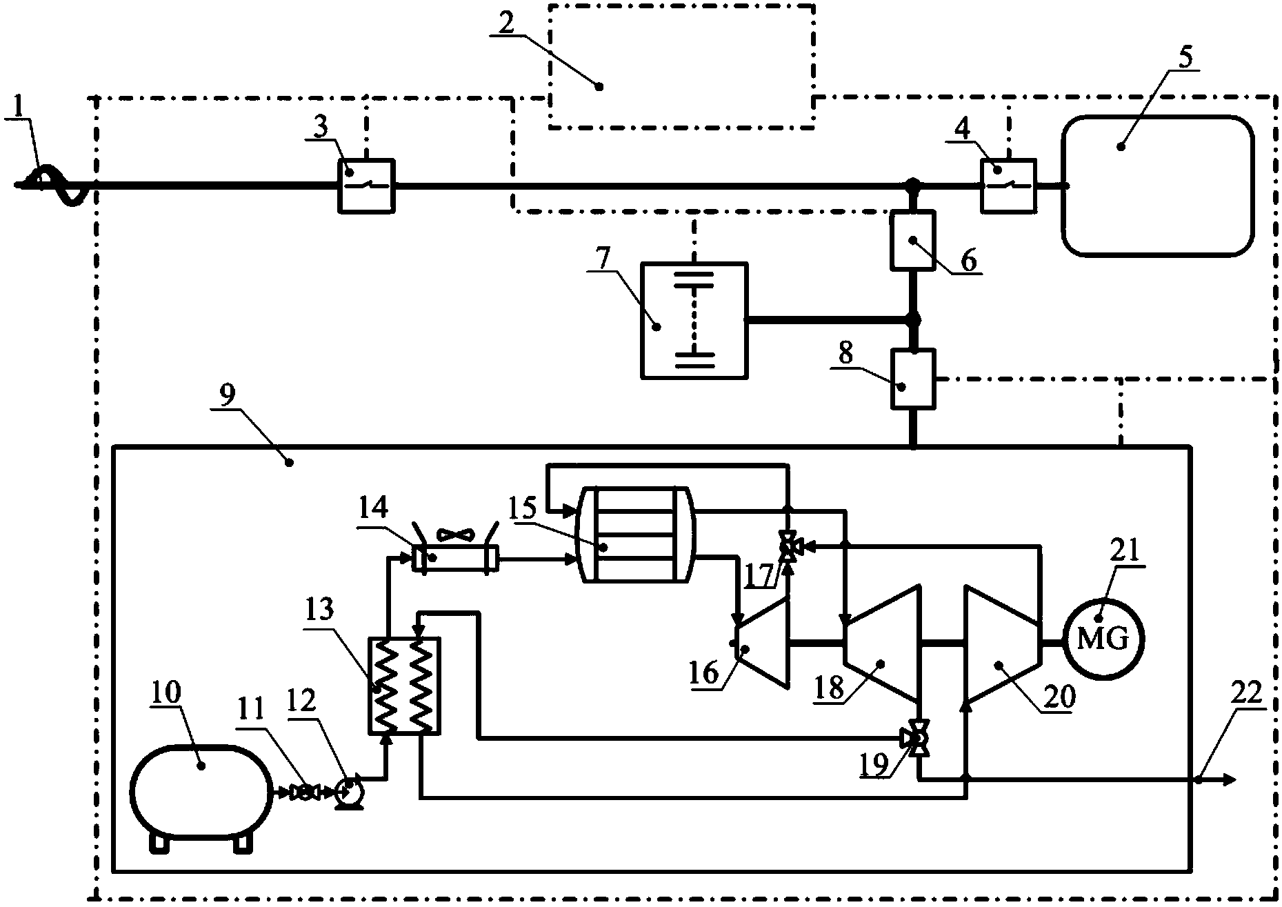
[0035] figure 1 It is a structural schematic diagram of Embodiment 1 of the uninterrupted power supply method and the power supply system of the present invention. The monitoring and control unit 2 monitors the working status of each unit in real time (the dotted line in the figure is the monitoring connection line). The monitoring and control unit 2 is connected to the supercapacitor unit 7 and the liquid nitrogen power unit 9 through the control circuit, and the monitoring and control unit 2 that is always in the working state is used to dynamically monitor the mains 1, the supercapacitor unit 7 and the liquid nitrogen power unit 9 in real time. working status. When the mains 1 is working normally, the electrical equipment 5 consumes the mains power; part of the mains 1 charges the supercapacitor through the power electronic device 6, and the other part passes through the power electronic device 8 and the heat storage and heat exchange unit in the liquid nitrogen power unit...
Embodiment 2
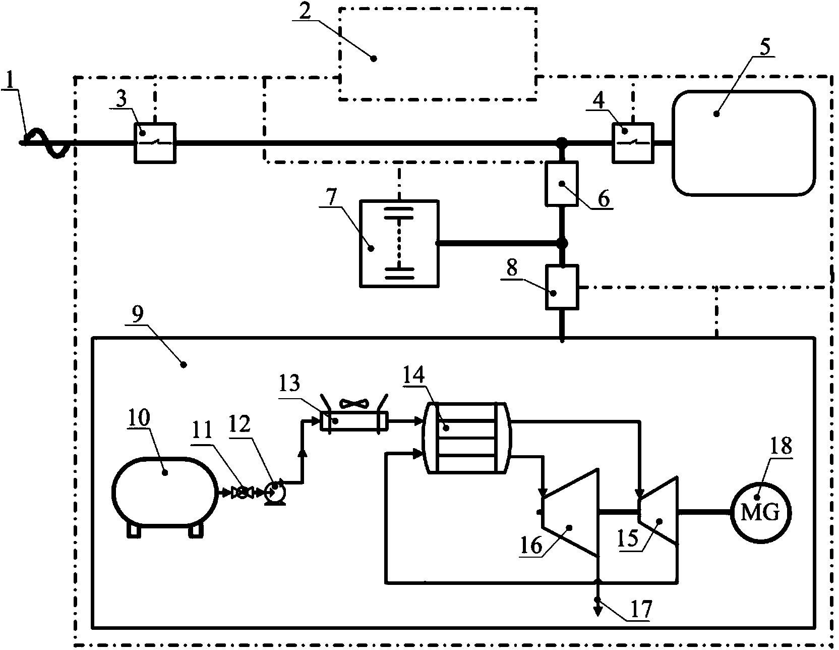
[0040] figure 2 It is a schematic structural diagram of Embodiment 2 of the uninterruptible power supply system of the present invention, its main structure is the same as that of Embodiment 1, the difference is the working process of the liquid nitrogen power unit 9 . When the liquid nitrogen power unit 9 is started, the liquid nitrogen in the cryogenic storage tank 10 passes through the valve 11 and is pressurized in the liquid pump 12. This part of the fluid passes through the air cooler 13, and the ambient air is used to heat the high-pressure liquid nitrogen to obtain high-pressure nitrogen. This part of nitrogen absorbs heat through the heat storage and heat exchange unit 14, and first works through the high-pressure expander 15. This part of the gas absorbs heat through the heat storage and heat exchange unit 14 again, then enters the low-pressure expander 16 to expand and perform work, and finally is discharged outside.
[0041] The number of stages of the expander in...
Embodiment 3
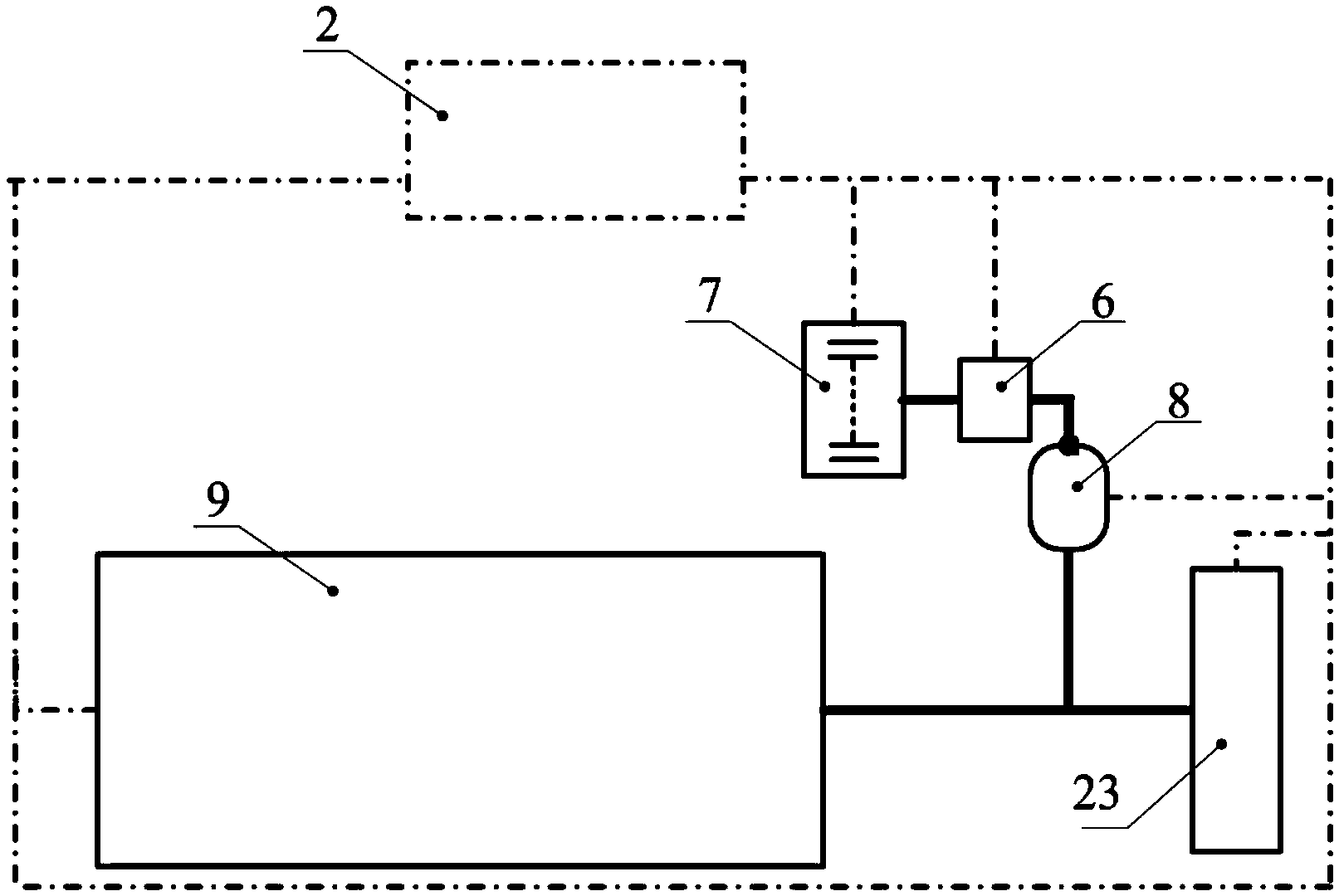
[0043] image 3 It is a structural schematic diagram of Embodiment 3 of the uninterruptible power supply system of the present invention. This embodiment is a mobile power system, which can be used as vehicle power, etc., and its power source 9 is a liquid nitrogen power unit. Compared with Embodiment 1 and the implementation For the liquid nitrogen power unit of example 2, the power unit 9 in this system has two cases including heat storage unit and no heat storage unit; when the heat storage unit is included, this part of heat energy comes from stored electric energy or other forms of heat energy ; When the heat storage unit is not included, an air cooler is included before the expander and between stages, and the ambient energy is used to heat the gas before each stage expands. The power generated by the power unit 9 is mainly output in the form of shaft work, and the moving power is provided by the rotating wheel 23. When the power system needs to decelerate and brake, the...
PUM
 Abstract
Description
Claims
Application Information