A silica container for pulling up monocrystalline silicon and method for manufacturing same
A silicon dioxide and manufacturing method technology, applied in chemical instruments and methods, self-melting liquid pulling method, single crystal growth, etc., can solve the problems of polluted ultra-high-purity silicon melt, etc., to reduce void defects, low Cost, effect of preventing air bubbles
- Summary
- Abstract
- Description
- Claims
- Application Information
AI Technical Summary
Problems solved by technology
Method used
Image
Examples
Embodiment 1)
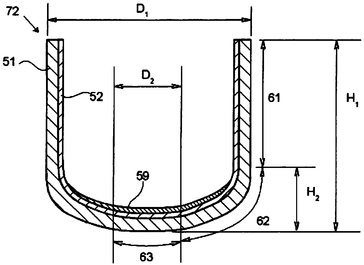
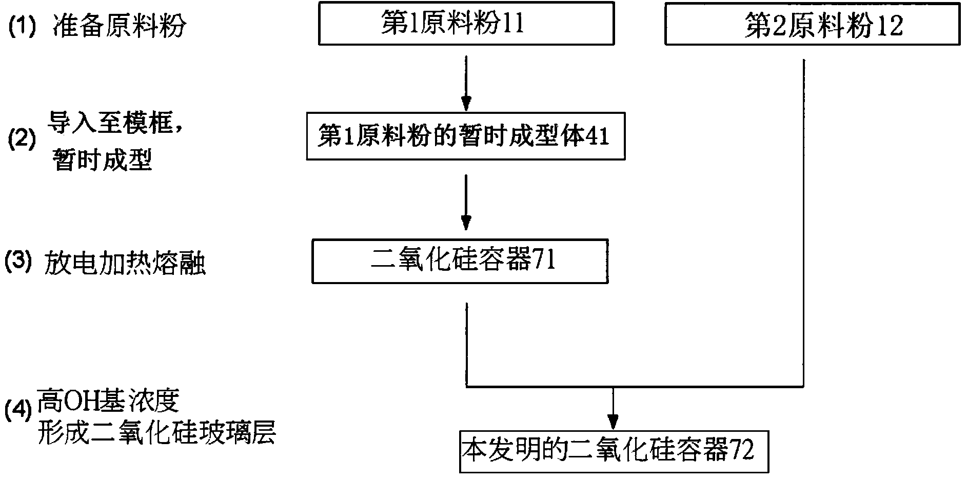
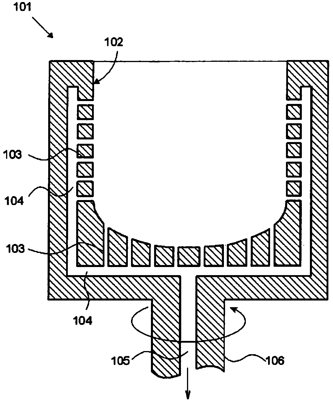
[0105] according to figure 2 In the steps (1) to (4) shown, a silica container for pulling a silicon single crystal is produced. As the first raw material powder 11 , natural quartz powder having a particle diameter of 50 to 500 μm and a purity of 99.999% by mass was prepared. while doing image 3 and Figure 5 The graphite frame 101 shown is rotated while the first powdered raw material 11 is put in to form a temporary molded body 41 of the powdered first raw material. Then, use Figure 6 and Figure 7 In the shown device, the internal environment of the temporary molded body 41 of the first raw material powder is set as dry N 2 95 volume (vol)%, H 2 5% by volume of the mixed gas is discharged and heated and melted inside the temporary molded body 41 while suctioning and reducing pressure from the outer peripheral portion. Thereby, the silica container 71 which made the outer side a white opaque silica sintered body and the inner side a colorless transparent silica gl...
Embodiment 2)
[0107] Using the same second raw material powder 12 (second raw material powder a, synthetic silica glass frit) as in Example 1, a silica container was manufactured basically in the same manner as in Example 1, except that the following points were changed. The first raw material powder 11 was mixed with an aluminum nitrate solution and dried in the same manner as in Example 1 to contain 10 mass ppm of Al. The environment during discharge heating is set to dry N 2 99% by volume, H 2 1% by volume of the mixed gas, the thickness of the high OH group concentration silica glass layer 59 at the center portion of the container bottom was set to 80 μm.
Embodiment 3)
[0109] Using the same first raw material powder 11 as in Example 1, a silica container was manufactured basically in the same manner as in Example 1, except for the following points. The second raw material powder 12 is a high-purity synthetic silica glass powder (second raw material powder b) containing 550 mass ppm of OH groups. A high OH group concentration silica glass layer 59 was formed from the entire inner surface of the bottom of the container to a part of the curved portion, especially at the center of the bottom of the container with a thickness of 460 μm.
PUM
| Property | Measurement | Unit |
|---|---|---|
| thickness | aaaaa | aaaaa |
| thickness | aaaaa | aaaaa |
| particle diameter | aaaaa | aaaaa |
Abstract
Description
Claims
Application Information
 - R&D
- Intellectual Property
- Life Sciences
- Materials
- Tech Scout
- Unparalleled Data Quality
- Higher Quality Content
- 60% Fewer Hallucinations
Browse by: Latest US Patents, China's latest patents, Technical Efficacy Thesaurus, Application Domain, Technology Topic, Popular Technical Reports.
© 2025 PatSnap. All rights reserved.Legal|Privacy policy|Modern Slavery Act Transparency Statement|Sitemap|About US| Contact US: help@patsnap.com


