A kind of thin wire resistance sleeve welding method and sleeve welding die

A thin wire and resistance technology, applied in resistance welding equipment, resistance electrode holders, manufacturing tools, etc., can solve the problems of mechanical properties that cannot meet the requirements of use, bending strength and toughness, and changes in joint shape, etc., to achieve easy automation, Material saving and good welding quality

Inactive Publication Date: 2015-10-21
WUHAN UNIV
View PDF5 Cites 0 Cited by
  • Summary
  • Abstract
  • Description
  • Claims
  • Application Information

AI Technical Summary

Problems solved by technology

But only wires with relatively large diameters can be welded. Resistance butt welding is used in wire rolling plants and the manufacture of wire products, but for particularly thin wires, the butt joint method cannot Meet various performance requirements such as flexural strength and toughness
Two wires are welded with a sleeve. Because the tube wall is very thin, the welding process is easily deformed, the shape of the joint changes, the quality of the joint is poor, and the mechanical properties cannot meet the requirements of use.

Method used


Image

  • A kind of thin wire resistance sleeve welding method and sleeve welding die
  • A kind of thin wire resistance sleeve welding method and sleeve welding die
  • A kind of thin wire resistance sleeve welding method and sleeve welding die

Examples


Embodiment Construction

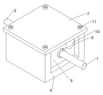
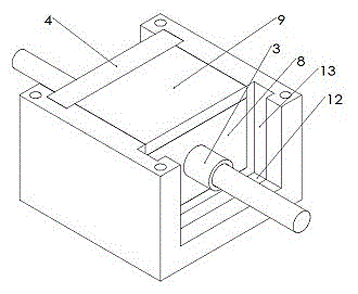
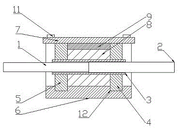
[0036] Specific embodiments of the present invention will be described in detail below in conjunction with the accompanying drawings.

[0037] Such as figure 1 , figure 2 , image 3 , Figure 4 As shown, a thin wire resistance sleeve welding mold includes an insulating base (6), a copper electrode plate (5), a tantalum electrode plate (4), a thin-walled sleeve (3), and a top cover (7); The insulating base (6) is groove-shaped, one end of the insulating base (6) is provided with a copper electrode plate (5), the other end is provided with a tantalum electrode plate (4), and the top of the insulating base (6) is provided with a top cover ( 7); the thin-walled sleeve (3) passes through the copper electrode plate (5) and the tantalum electrode plate (4); in the space formed by the copper electrode plate (5), the tantalum electrode plate (4) and the top cover Filled with cement to form a cement module (8); the copper electrode plate (5) is provided with conductive screw holes...


PUM


Abstract

The invention provides a fine wire resistance socket welding method and a socket welding mould. Expansion cement is used for wrapping a sleeve-connection thin-wall sleeve pipe in a clamp provided with the fine wire resistance socket welding mould, pre-stress is formed in the sleeve pipe through the mould, the sleeve pipe is prevented from expanding in the welding process, and therefore a perfect welding connector with the unchanged appearance size of the sleeve pipe for welding wires and welding a wire and the sleeve pipe is obtained. A fixing insulation block is formed by utilizing the expansion cement, the expansion of the sleeve pipe is limited, current is concentrated to heat the welding position, and the connector and the mould are simple in structure, convenient to install and easy to operate. After welding is finished, the welded metal wire can be taken out only by breaking the cement block to pieces, and the whole mould is low in manufacturing cost and can be produced in a batch mode.

Description

technical field [0001] The invention relates to the field of filament welding and moulds, in particular to a filament resistance sleeve welding method and a sleeve welding fixture. Background technique [0002] The current gas shielded laser welding filament method is to align the metal filaments in the welding area, and then perform laser welding, which is characterized in that the welding work area must use gas shielded welding, and its mechanical properties are difficult to meet the requirements of mechanical properties. [0003] In the prior art, a tube is used to connect two wire parts, glue is poured into the tube, and then the two filaments are inserted into the tube for connection. It is well known that the bonding strength is low, so the length and wall thickness of the casing cannot be improved. The joint strength of the two guide wire parts makes it difficult to obtain sufficient bending and torque transmission; at the same time, the tubular connection part length...

Claims


Application Information

Patent Timeline
Patent Type & Authority Patents(China)
IPC IPC(8): B23K11/02B23K11/36
CPCB23K11/0073B23K11/02B23K11/30B23K11/31B23K11/36
Inventor 朱援祥梨桥成正辉
Owner WUHAN UNIV
Why Eureka
Try Eureka