Central system based on wireless torque detection

A technology of a mid-mounted system and a wireless transmitter, which is applied in the directions of rider driving, transportation and packaging, and vehicle components, can solve the problems of inability to achieve power assistance, complex mechanical structure, and undetectable, and achieve a large torque detection range, The effect of optimizing the delivery method and reducing the load on the human body

Active Publication Date: 2014-03-26
SUZHOU WANJIA ELECTRIC
View PDF6 Cites 16 Cited by
  • Summary
  • Abstract
  • Description
  • Claims
  • Application Information

AI Technical Summary

Problems solved by technology

However, when encountering high-resistance and heavy-load road conditions such as headwind or uphill, the driving force output by the motor is also small because the speed of the person riding is low, and the purpose of power assistance cannot be achieved at all, and the riding effect is poor. Accepted by the mainstream market
The torque detection based on the magnetic ring and Hall scheme has a complex mechanical structure, requires a spring and a pair of magnetic rings to cooperate with each other, and requires high installation accuracy, and it is prone to shortcomings such as measurement errors caused by vehicle falls in the later stage.
[0008] In addition, the following problems also exist in the existing mid-mounted system based on wireless torque detection: 1. The torque sensor is directly arranged on the center shaft. A shaft torque sensing system and its quadratic signal transmission method. The torque sensing system in this application includes a torque sensor installed on the center shaft of a bicycle, a wireless signal transmitter electrically connected to the torque sensor, and a wireless signal transmitter installed on the bicycle The wireless signal receiver near the central axis of the car body, when the system is stepped on the left pedal hard, the torque transmission process is: left pedal-central axis-torque sensor-crank plate, that is, the torque sensor is in the The torque can be detected before the crankset rotates, and the motor can be driven in time to assist manpower riding; but when the manpower is sent from the right pedal, the torque transmission process is the right pedal-center shaft-crankset, so the tooth When the disc has rotated, the torque sensor cannot detect the torque, so the motor cannot be driven. The existing solution is to simulate the left and right torque through software after starting, so the existing torque transmission method cannot achieve zero start. The riding effect is poor, and most people are used to start the bicycle with the right foot, so, based on the above analysis, this method has no advantage; In this way, when the speed of people stepping on the pedal is greater than the speed of the motor, human power will drive the motor to rotate, which increases the burden on the human body.
In particular, when the power of the central system is turned off, people will bear the load of the motor rotation during riding, which makes it more difficult to ride than ordinary bicycles; 3. The signal processing method of the existing central system is generally After simple signal processing, the detected torque signals are all sent to the controller, and the controller processes and controls the signals in a unified manner, so the dependence of the central system on the controller is improved to a certain extent, and at the same time Certain requirements are also put forward for the functions of the controller, which narrows the selection range of the controller, thus weakening the versatility of the mid-mounted system; 4. The existing mid-mounted system uses a Hall sensor to detect the rotation speed signal of the crankshaft. , that is, the design of the sensor has only one signal output, which cannot realize the double control of the rotation speed and rotation direction of the crankshaft, so that it cannot assist the control of the motor well, and even dangerous phenomena such as misoperation and speeding may occur.

Method used


Image

  • Central system based on wireless torque detection
  • Central system based on wireless torque detection
  • Central system based on wireless torque detection

Examples


Embodiment Construction

[0034] The technical solutions of the embodiments of the present invention will be clearly and completely described below in conjunction with the accompanying drawings of the present invention.

[0035] The orientation description in the present invention is according to Figure 1~6 The orientation in is described in detail, that is, Figure 1~6 The up, down, left, and right directions in are the up, down, left, and right directions described in the present invention.

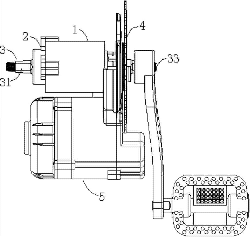
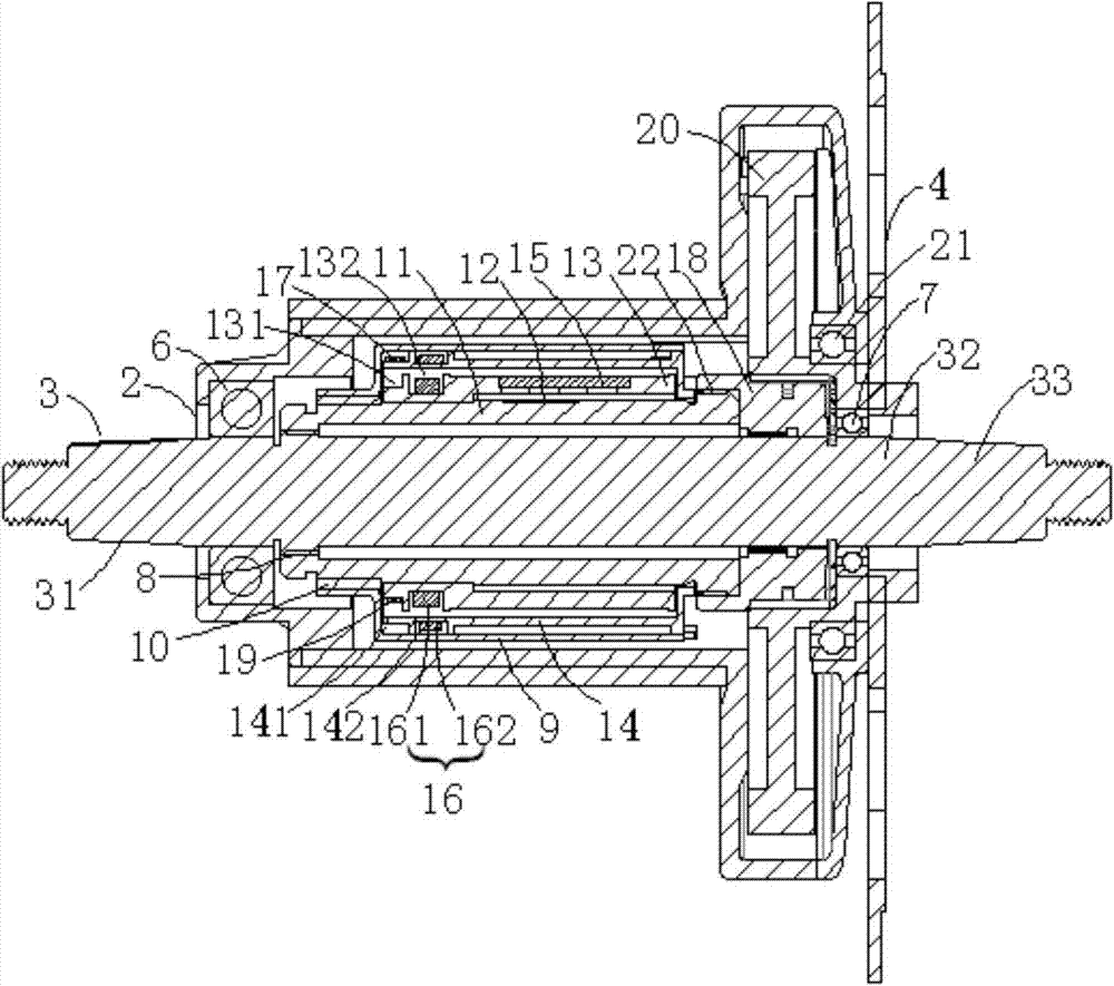
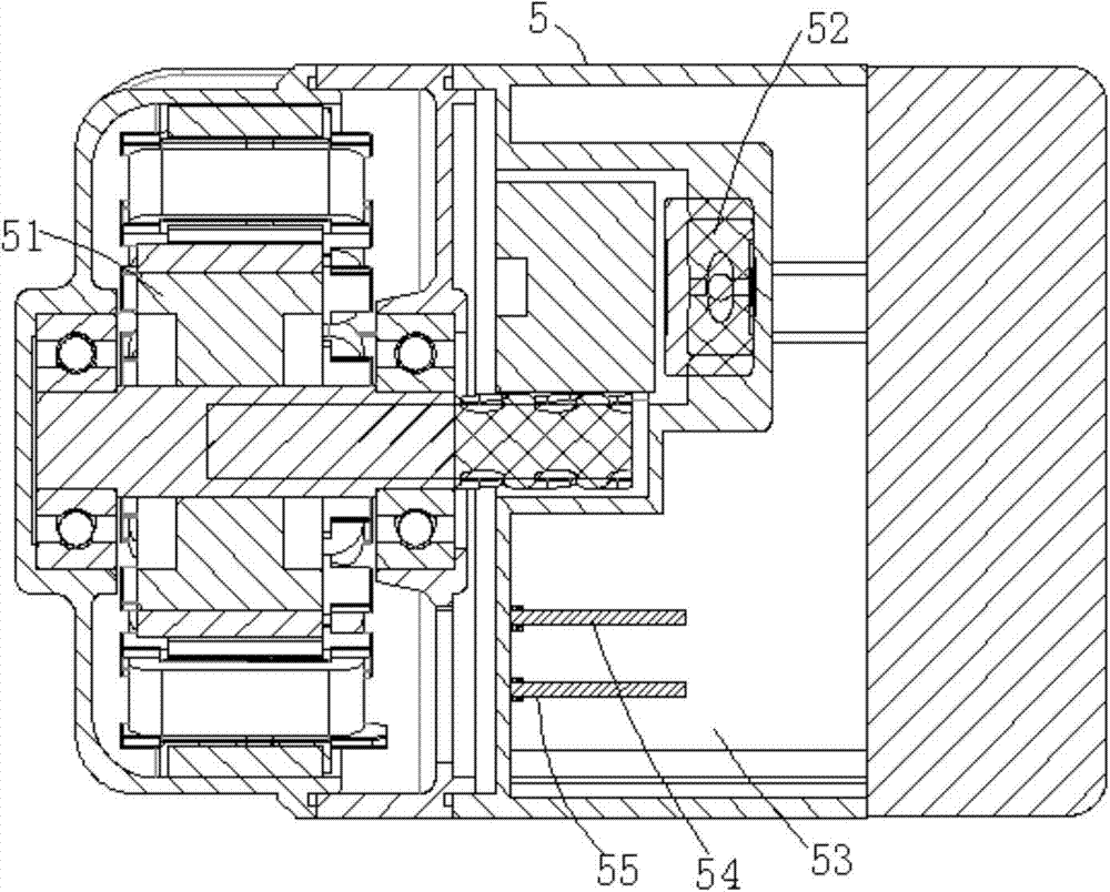
[0036] A mid-mounted system based on wireless torque detection disclosed by the present invention is mainly used on power-assisted bicycles, and provides the kinetic energy required for the bicycle to travel through the driving mode of electric power assisting manpower. It can realize zero start, and the riding effect is excellent; it is also suitable for all road conditions, and can obtain better boosting effect when riding at low speed or high speed. It has the advantages of convenient installation and maint...


PUM


Abstract

The invention discloses a central system based on wireless torque detection. The system comprises a first shell, an intermediate shaft, a crankset and a second shell, wherein the intermediate shaft penetrates through the first shell, the crankset is fixed to the intermediate shaft through a clutch, the second shell is fixedly connected with the first shell, the first shell comprises a torsion barrel, a torque transducer and a first clutch, the torsion barrel is arranged on the intermediate shaft in a sleeved mode, and one end of the torsion barrel is fixedly connected to the first clutch; the torque transducer is fixed to the torsion barrel, and when the intermediate shaft is stressed, the torque is transmitted in the sequence of a left/right side pedal-the intermediate shaft-the torsion barrel-the first clutch-the crankset. The system can achieve zero starting, and the riding effect is outstanding; the system adapts to all road conditions, better assistance effect can be obtained on both low-speed riding and high-speed riding, the system has the advantages of being convenient to install and maintain, stable in work and the like, and the real relax riding purpose can be achieved for a user.

Description

technical field [0001] The invention relates to the technical field of power-assisted bicycle drive, in particular to a mid-mounted system based on wireless torque detection that can realize zero start. Background technique [0002] Power-assisted bicycles, also known as power-assisted electric bicycles, are a riding tool between bicycles and electric vehicles. They provide the kinetic energy needed for bicycles through electric power to assist manpower. The product of an environmentally friendly lifestyle. The central system is the core component of the power-assisted bicycle, which integrates torque detection, controller, and motor drive to control the normal driving of the vehicle. [0003] At present, power-assisted bicycles are more popular in foreign markets, such as Germany, Japan and other relatively developed countries. In my country, electric bicycles still occupy the main market, and most electric bicycles are driven by wheel hubs, which have obvious disadvantag...

Claims


Application Information

Patent Timeline
Patent Type & Authority Applications(China)
IPC IPC(8): B62M6/50B62M6/80
Inventor 黄福明李云飞黄俊宁蔡华林张强
Owner SUZHOU WANJIA ELECTRIC
Why Eureka
Try Eureka