Pupil shaping unit structure of lithography machine and design method for diffraction optical element of pupil shaping unit structure

A diffractive optical element and shaping unit technology, applied in the field of lithography machine, can solve the problems of light field collapse, affecting the non-uniformity of the illumination pupil, and unable to apply the illumination system of the deep ultraviolet lithography machine, etc.

Active Publication Date: 2014-03-26
SHANGHAI INST OF OPTICS & FINE MECHANICS CHINESE ACAD OF SCI
View PDF8 Cites 15 Cited by
  • Summary
  • Abstract
  • Description
  • Claims
  • Application Information

AI Technical Summary

Problems solved by technology

This method is to use optical fiber to split the laser beam. However, due to the large divergence angle of the output beam of the optical fiber, it will cause the collapse of the light field when i

Method used


Image

  • Pupil shaping unit structure of lithography machine and design method for diffraction optical element of pupil shaping unit structure
  • Pupil shaping unit structure of lithography machine and design method for diffraction optical element of pupil shaping unit structure
  • Pupil shaping unit structure of lithography machine and design method for diffraction optical element of pupil shaping unit structure

Examples


Embodiment Construction

[0056] The present invention will be further described below in conjunction with the accompanying drawings and embodiments, but the protection scope of the present invention should not be limited thereto.

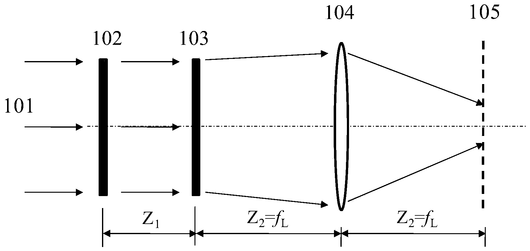
[0057] see first figure 1 , figure 1 It is a schematic diagram of the optical path structure of the pupil shaping unit of the lithography machine of the present invention, which is used to generate the required pupil surface light intensity distribution in the ultraviolet lithography machine. Depend on figure 1 It can be seen that the pupil shaping unit includes a first diffractive optical element 102 , a second diffractive optical element 103 , and a zoom collimator lens group 104 . After the incident light beam 101 passes through the first diffractive optical element 102 and the second diffractive optical element 103 whose light-passing surface is set to be perpendicular to the optical axis of the illumination system, it is irradiated on the zoom collimating lens group ...


PUM


Abstract

The invention discloses a pupil shaping unit structure of a lithography machine and a design method for a diffraction optical element of the pupil shaping unit structure. The pupil shaping unit structure comprises a cascade diffraction optical element and a varifocal collimating lens group, wherein the cascade diffraction optical element comprises a first diffraction optical element and a second diffraction optical element; the light transmittance surfaces of the two diffraction optical elements are perpendicular to the optical axis of a lighting system; the two diffraction optical elements are pure phase elements. The design method for the cascade diffraction optical element comprises the following steps of calculating a period of a phase unit; enabling a light beam to be incident, determining the light intensity distribution of the required optical beam and performing discretization processing; entitling initial phase matrixes of the first diffraction optical element and the second diffraction optical element; performing quantification processing through an iteration algorithm to obtain quantified phase matrixes of the first diffraction optical element and the second diffraction optical element; evaluating a design result.

Description

technical field [0001] The invention relates to a lithography machine, in particular to a pupil shaping unit structure of a lithography machine and a design method for a diffractive optical element thereof. Background technique [0002] In the lighting system of the lithography machine, it is necessary to adopt an off-axis lighting mode to enhance the resolution of the lithography, increase the depth of focus, and improve the contrast of the lithography pattern, thereby improving the quality of the lithography pattern. The pupil shaping unit in the lighting system of the lithography machine needs to provide traditional lighting (that is, on-axis lighting mode), and off-axis lighting modes such as ring lighting, dipole lighting, and quadrupole lighting. The diffractive optical element (Diffractive Optical Element, referred to as DOE) in the pupil shaping unit cooperates with the zoom collimator lens group to realize the various illumination modes described above. DOE has the...

Claims


Application Information

Patent Timeline
IPC IPC(8): G03F7/20G02B27/09G02B27/00
Inventor 司徒国海蔡燕民黄惠杰王向朝
Owner SHANGHAI INST OF OPTICS & FINE MECHANICS CHINESE ACAD OF SCI
Why Eureka
Try Eureka