Supercharge Your Innovation With Domain-Expert AI Agents!

Optical filter

An optical filter and light source technology, applied in the field of optical filters, can solve problems such as image quality degradation, and achieve the effect of excellent productivity and economy

Active Publication Date: 2014-04-09
ASAHI GLASS CO LTD
View PDF7 Cites 13 Cited by
  • Summary
  • Abstract
  • Description
  • Claims
  • Application Information

AI Technical Summary

Problems solved by technology

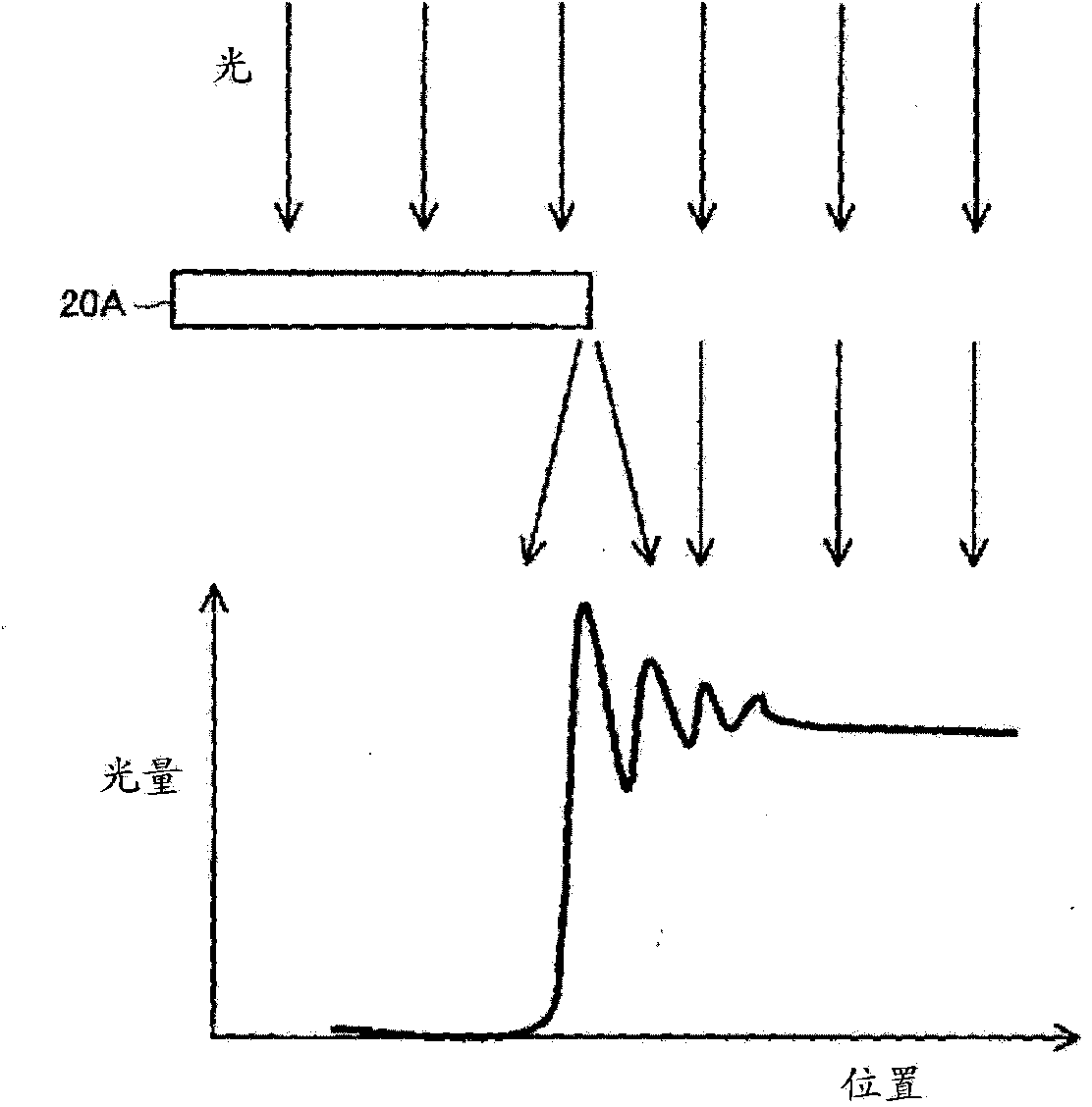
[0005] However, in the optical filter integrated with the black covering as described above, a phenomenon of light diffraction occurs near the boundary between the black covering and the light-transmitting opening, and unnecessary light may enter the imaging element and cause the image to be blurred. quality reduction

Method used


Image

  • Optical filter
  • Optical filter
  • Optical filter

Examples


Embodiment 1)

[0121] On one surface of a 40mm×40mm×0.3mm gusseted infrared-absorbing glass (NF-50 glass manufactured by Asahi Glass Co., Ltd.), silicon dioxide (SiO2) is alternately laminated by vacuum deposition. 2 ; refractive index 1.45 (wavelength 550nm)) layer and titanium dioxide (TiO 2 ; Refractive index 2.32 (wavelength 550nm)) layer to form a dielectric multilayer film (34 layers). In addition, an antireflection film is formed on the other surface of the infrared-absorbing glass.

[0122] On the entire surface of the above-mentioned dielectric multilayer film, a light-shielding ultraviolet curable acrylate resin was coated with a thickness of 1.2 μm by spin coating, and after heating, a photomask having irregular irregularities on the inner peripheral surface of the opening was applied. Irradiate its surface with a high-pressure mercury lamp at 100mJ / cm 2 UV light to cure it. Thereafter, unexposed portions were removed with a developing solution, followed by heating to manufactu...

Embodiment 2)

[0125] Carried out in the same manner as in Example 1, silicon dioxide (SiO 2 ; refractive index 1.45 (wavelength 550nm)) layer and titanium dioxide (TiO 2 ; Refractive index 2.32 (wavelength 550nm)) layer to form a dielectric multilayer film (34 layers). In addition, a three-layer anti-reflection film is formed on the other surface of the infrared-absorbing glass.

[0126] On the surface of the above-mentioned dielectric multilayer film, use the first screen plate with irregular unevenness on the inner peripheral surface of the opening to coat and add light-shielding resin ink (containing black coloring pigment), silica fine powder (average particle size (D50 ) 4.7 μm) and a solvent and uniformly mix the prepared coating solution, and heat to form the first coating film. Next, use a second screen with a smaller opening than the first screen to coat the above-mentioned coating solution on the first coating film again, heat it to form a second coating film, and manufacture a ...


PUM

PropertyMeasurementUnit
Heightaaaaaaaaaa
Widthaaaaaaaaaa
Surface roughnessaaaaaaaaaa

Abstract

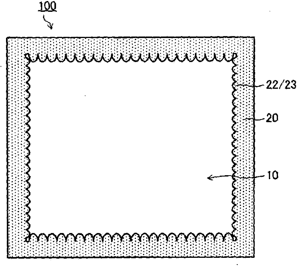
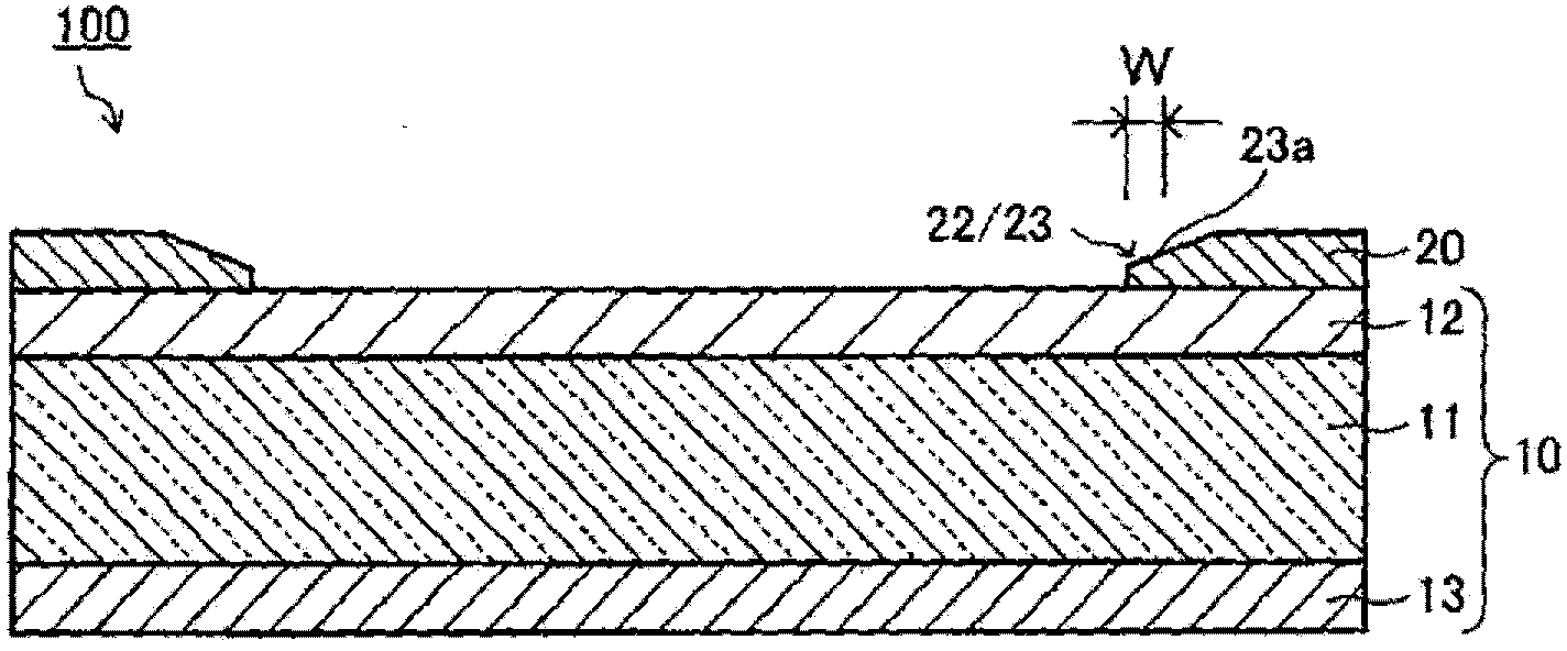
Provided is an optical filter having excellent productivity and economic efficiency and integrally provided with a light blocking film capable of suppressing stray light that causes image quality degradation. An optical filter (100) is an optical filter used for an image pickup device having a built-in image pickup element on which light from a subject or a light source is incident. The optical filter (100) comprises an optical filter main body (10) disposed between the subject or the light source and the image pickup element and having a transmission property for incident light, and a frame-shaped light blocking film (20) integrally formed on at least one surface of the optical filter main body (10). The frame-shaped light blocking film (20) satisfies the following condition (1) and / or condition (2). (1) Fine asperities (22) are formed on at least part of the inner peripheral surface of the frame-shaped light blocking film (20) in plan view. (2) A thin portion (23) is formed at at least part of the inner edge of the frame-shaped light blocking film (20).

Description

technical field [0001] The present invention relates to optical filters. Background technique [0002] In imaging devices using solid-state imaging elements such as CCDs (Charge Coupled Devices) and CMOS image sensors (Complementary Metal Oxide Semiconductor Image Sensors, Complementary Metal Oxide Semiconductor Image Sensors), in order to reproduce color tones well and obtain sharp For an image, a filter (filter) having various optical functions is arranged between the imaging lens and the solid-state imaging device, etc. A typical example is a filter (near-infrared cut filter) that blocks light in the near-infrared wavelength region in order to correct the spectral sensitivity of the solid-state imaging element to human visibility, and is usually arranged between the imaging lens and the solid-state imaging element . In addition, the imaging device is equipped with a shielding member called a diaphragm, which is used to adjust the amount of incoming light to prevent the ...

Claims


Application Information

Patent Timeline
IPC IPC(8): G02B5/22G02B5/00
CPCG02B5/22G02B5/00G02B5/005G02B5/205G02B5/003G03B11/00G02B5/208
Inventor 松尾淳梅田悟史木梨勉
Owner ASAHI GLASS CO LTD
Features
  • R&D
  • Intellectual Property
  • Life Sciences
  • Materials
  • Tech Scout
  • Unparalleled Data Quality
  • Higher Quality Content
  • 60% Fewer Hallucinations
Learn More