

Clean coal gas production method
A production method and coal gas technology, applied in the field of coal gasification, can solve the problems of difficulty in ash removal, limitations of equipment and boiling conditions, and high amount of carryover, and achieve the effects of reducing the number of large equipment, facilitating factory production, and improving heat recovery
- Summary
- Abstract
- Description
- Claims
- Application Information
AI Technical Summary
Problems solved by technology
Method used
Image

Examples
Embodiment 1
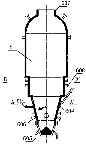
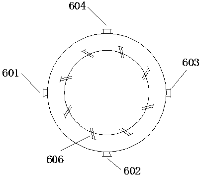
[0033] Such as Figure 1-4 The method for producing clean gas by using the present invention as shown includes pneumatically transporting qualified pulverized coal to the coal scuttle 1, then to the coal storage tank 2, and sending it into the gasifier at 90° in three directions via the coal feeder 4 The three coal inlets 601-603 of 6 that are 90° to each other enter the gasifier 6. The gasification agent oxygen and steam are introduced into the mixer 3 through the outside, and are divided into two paths to enter the primary gasification zone and the secondary gasification zone (the other path with a higher pressure mixed gasification agent also enters the secondary gasification zone) for Complex reactions such as oxidation and reduction produce gas.
[0034]The direction and angle of primary gasification agent injection is an important factor to realize the vortex to hold up the pulverized coal, which is equivalent to the tornado effect; however, due to the single-point coal...
Embodiment 2
[0043] Such as Figure 1-3 The device for producing clean gas as shown includes a gasifier 6, the gasifier 6 is connected to a medium-pressure waste heat boiler 11 through a reflux cyclone 7 and a high-temperature cyclone 8 in sequence, and the medium-pressure waste heat boiler 11 is connected to a low-pressure waste heat boiler 20 through a metal membrane dust collector 17, and the low-pressure waste heat boiler 21 is connected to a cooler 22. The gasifier 6 is an inverted ladder structure, the lower end of which is a truncated cone structure, and the truncated cone structure is provided with three coal feeding ports 601-603 at 90° to each other, a dust return port 604, and three sets of coal hoppers. , the coal storage tank system can provide stable operation for the coal feeder; multi-point coal feeding provides convenience for the uniform distribution of solid materials, which can make the material layer thin and even, fully contact with the gasification agent, and achieve...
Embodiment 3
[0045] The concrete technical scheme of the present invention is described further below in conjunction with implementation example:
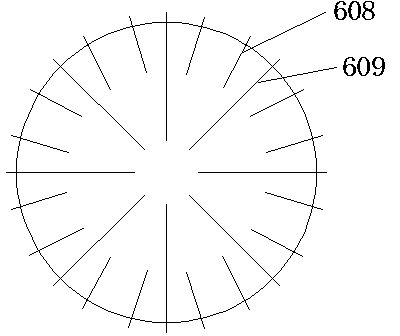
[0046] Raw gas generation part, the output is 50000Nm 3 In the ladder-type gasification furnace 6 of / h·unit, oxygen and steam are fed into the gasification furnace 6 evenly and in layers in the mixer 3, so that the solid material is fully boiled and the gasification reaction is carried out in time, and the reaction temperature reaches 950°C. In the secondary gasification zone, under the condition of uniform solid material, the pressure gasification agent has changed the defect that the original gasification agent cannot reach the center, making the gas-solid reaction more complete, and the reaction temperature can reach 1050°C. Part of the gas continues to react at the top of the furnace. The main components of the gas are: CO, 34%; H 2 , 40%; CO 2 , 23%; CH 4 , 2%, N 2 , 1% to achieve uniform and high-efficiency gasification of the whole ...
PUM
 Abstract
Description
Claims
Application Information