Fuel injection device for internal combustion engine

A technology for a fuel injection device and a fuel injection valve, which is applied to the fuel injection device, the addition of non-fuel substances to the fuel, the charging system, etc., can solve the problems of increasing smoke and black smoke, decreasing fuel injection pressure, and deteriorating flammability, etc. Achieve the effect of preventing the increase of smoke and black smoke and preventing the drop of fuel injection pressure

Inactive Publication Date: 2014-04-16
MITSUBISHI HEAVY IND LTD
View PDF9 Cites 2 Cited by
  • Summary
  • Abstract
  • Description
  • Claims
  • Application Information

AI Technical Summary

Problems solved by technology

[0008] However, as in the technologies disclosed in the above-mentioned Patent Document 1 and Patent Document 2, in a fuel injection valve that injects multi-layered or emulsified fuel composed of fuel oil and water, since the injection amount at one time increases, it is necessary to The diameter of each injection hole is made larger than that of the fuel injection valve that injects only fuel
Therefore, in the technologies disclosed in the above-mentioned Patent Document 1 and Patent Document 2, when going out of the engine exhaust gas restricted sea area from the engine exhaust gas restricted sea area, the fuel injection mode (operating mode) of the main engine and the generator is changed from the injection to the fuel and When the multi-layered or emulsified fuel formed by water is changed to only fuel injection, it may lead to a drop in fuel injection pressure, deterioration of combustibility, and deterioration of internal combustion engine performance, as well as increased smoke and black smoke

Method used


Image

  • Fuel injection device for internal combustion engine
  • Fuel injection device for internal combustion engine
  • Fuel injection device for internal combustion engine

Examples


Embodiment Construction

[0061] [First Embodiment]

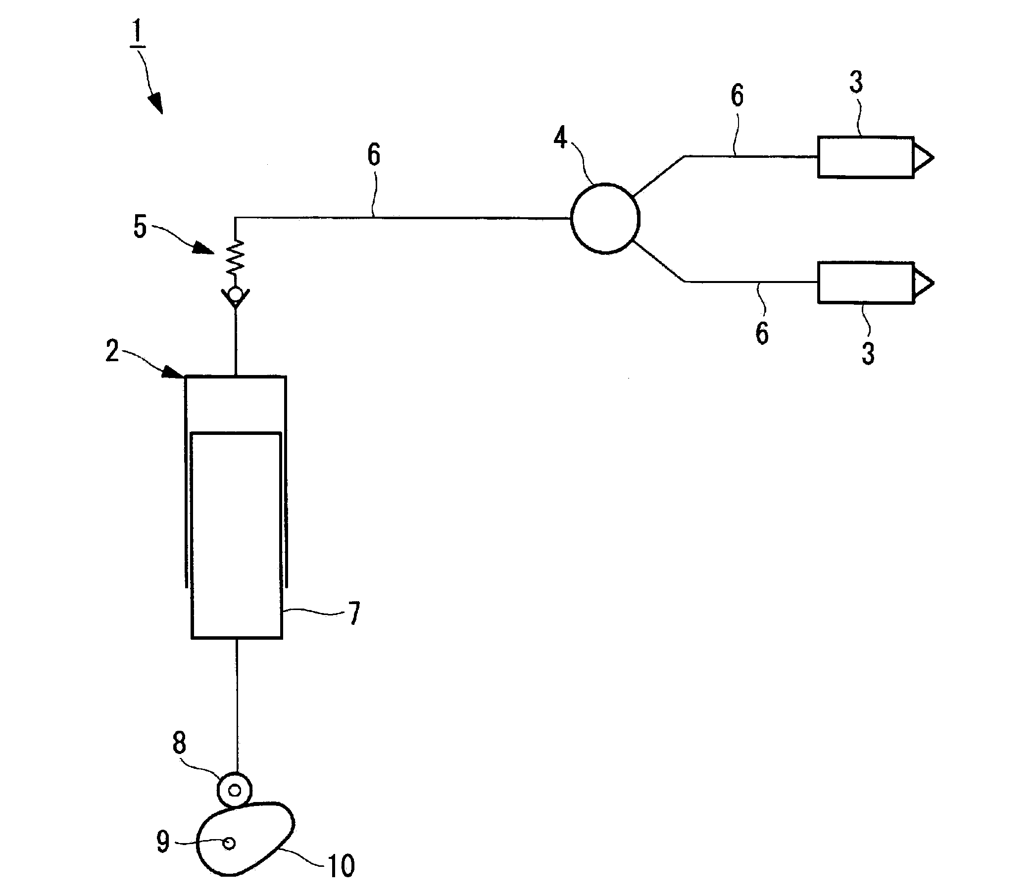
[0062] Now refer to figure 1 and figure 2 A fuel injection device for an internal combustion engine according to a first embodiment of the present invention will be described.

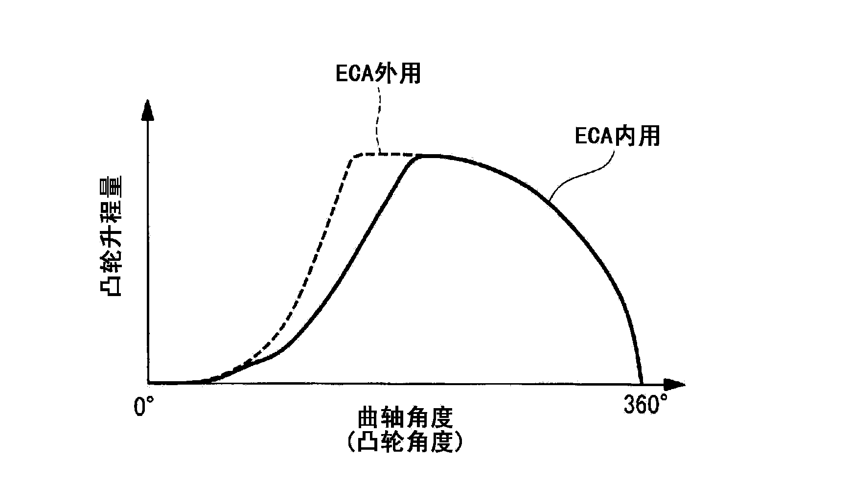
[0063] figure 1 is a schematic configuration diagram showing a fuel injection device for an internal combustion engine according to the present embodiment, figure 2 yes means figure 1 A graph showing the relationship between the amount of cam lift and the angle of the crankshaft (cam angle) for the cam shown.

[0064] In addition, the fuel injection device for an internal combustion engine of the present invention is mounted on an internal combustion engine (not shown) such as a large marine diesel engine.

[0065] Such as figure 1 As shown, the fuel injection device 1 of the internal combustion engine of the present embodiment, before entering the engine exhaust gas restricted sea area from outside the engine exhaust gas restricted sea area, for example, as disclose...


PUM


Abstract

The present invention prevents the performance of an internal combustion engine from being degraded and prevents soot and dust, and black smoke from increasing due to the reduction of fuel injection pressure and the deterioration of combustibility even when only fuel oil is injected into a cylinder liner. A fuel injection device (1) for an internal combustion engine can selectively inject fuel oil and inert matter in a multilayered state or an emulsified state or only fuel oil from a fuel injection valve (3). A cam (10) which thrusts up a plunger (7) of a fuel injection pump (2) for pressurizing and supplying, to the fuel injection valve (3), the fuel oil and the inert matter in the multilayered state or the emulsified state or the fuel oil is provided with a first cam which is used at the time of thrusting up the fuel oil and the inert matter in the multilayered state or the emulsified state, and a second cam which is used at the time of thrusting up only the fuel oil.

Description

technical field [0001] The present invention relates to a fuel injection device for an internal combustion engine equipped with a plurality of fuel injection valves per cylinder. Background technique [0002] As a fuel injection device for an internal combustion engine equipped with a plurality of fuel injection valves per cylinder, for example, a device disclosed in Patent Document 1 is known. [0003] Patent Document 1: Japanese Patent Application Publication No. 8-11945 [0004] Patent Document 2: Japanese Patent No. 3615260 [0005] The problem to be solved by the invention [0006] In recent years, from the viewpoint of environmental protection, an engine exhaust control area (ECA: Emission Control Area) has been stipulated, and NOx emission is restricted in this environment control area. [0007] In addition, in the sea area where engine exhaust gas is restricted, in the near future, it is planned to further strengthen the restriction of exhaust gas. In order to com...

Claims


Application Information

Patent Timeline
Patent Type & Authority Applications(China)
IPC IPC(8): F02M25/022F02B47/04F02M43/02F02M43/04
CPCF02M43/02F02M43/04F02B47/04F02M25/022
Inventor 村田聪樋口纯高石龙夫赤川裕和长船信之介
Owner MITSUBISHI HEAVY IND LTD
Why Eureka
Try Eureka